 Madhava Publications
 Grow Career Publication
1. Electrostatic Potential
- Books Name
- Physics Book Part l and ll
- Publication
- Grow Career Publication
- Course
- CBSE Class 12
- Subject
- Physics
Chapter 2: Electrostatic Potential and Capacitance
Electrostatic Potential
We define potential energy of a test charge q in terms of the work done on the charge q. This work is obviously proportional to q, since the force at any point is qE, where E is the electric field at that point due to the given charge configuration. It is, therefore, convenient to divide the work by the amount of charge q, so that the resulting quantity is independent of q. In other words, work done per unit test charge is characteristic of the electric field associated with the charge configuration
POTENTIAL DUE TO A POINT CHARGE
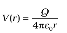
Take Q to be positive. We wish to determine the potential at any point P with position vector r from the origin. For that we must calculate the work done in bringing a unit positive test charge from infinity to the point P. For Q > 0, the work done against the repulsive force on the test charge is positive.
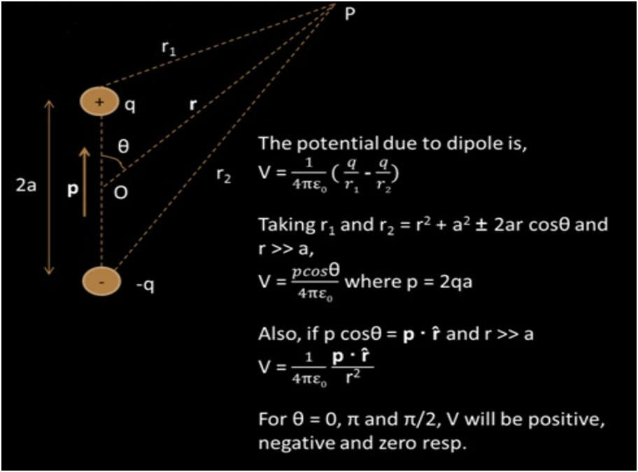
Potential due to an electric dipole
What is the electric potential due to an electric dipole at an equatorial point? Zero, as potential on equatorial point, due to charges of electric dipole, are equal in magnitude but opposite in nature and hence their resultant is zero.
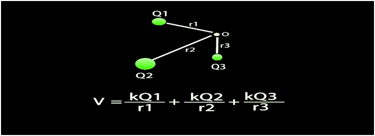
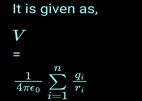
Potential due to system charges
derive an expression for the electric field at a point due to a system of n point charges. When there is a group of point charges say q1, q2, q3,….qn is kept at a distance r1, r2, r3,……rn, we can get the electrostatic potential at any particular point.
Equipotential surface.
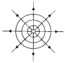
If the points in an electric field are all at the same electric potential, then they are known as the equipotential points. If these points are connected by a line or a curve, it is known as an equipotential line. If such points lie on a surface, it is called an equipotential surface.
Work Done in Equipotential Surface
The work done in moving a charge between two points in an equipotential surface is zero. Then the work done in moving the charge is given by
W = q0(VA –VB)
As VA – VB is equal to zero, the total work done is W = 0.
2. Potential energy
- Books Name
- Physics Book Part l and ll
- Publication
- Grow Career Publication
- Course
- CBSE Class 12
- Subject
- Physics
Potential energy
Potential energy of a system charge
Electric Potential Energy of a System of Charges Electric potential energy of a system of charges is equal to amount of work done in forming the system of charges by bringing them at their particular positions from infinity without any acceleration and against the electrostatic force. It is denoted by U.
U=W=qV(r)
Potential energy in an external field
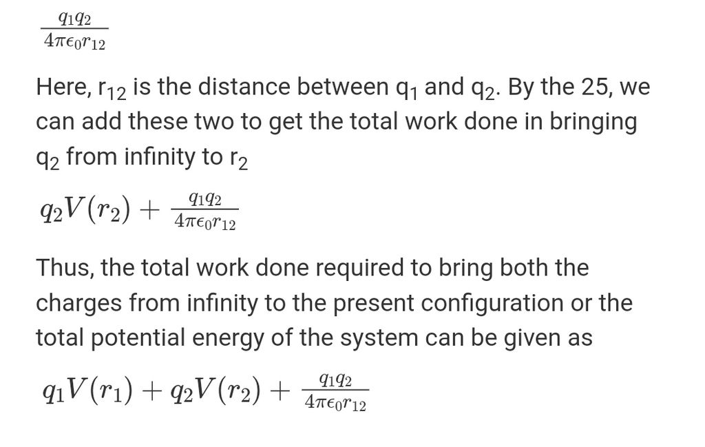
consider a system of two charges q1 and q2 located at a distance r1 and r2 from the origin. Let these charges be placed in an external field of magnitude E. Let the work done in bringing the charge q1 from infinity to r1 be given as q1V(r1)and the work done in bringing the charge q2 from infinity to r2 against the external field can be given as q2V(r2).
Potential energy of a dipole in an external field
Consider a dipole with charges q1 = +q and q2 = –q placed in a uniform electric field E, in a uniform electric field, the dipole experiences no net force; but experiences a torque τ given by τ = p×E which will tend to rotate it (unless p is parallel or antiparallel to E).
ELECTROSTATICS OF CONDUCTORS
1. Inside a conductor, electrostatic field is zero
There may also be an external electrostatic field. In the static situation, when there is no current inside or on the surface of the conductor, the electric field is zero everywhere inside the conductor. This fact can be taken as the defining property of a conductor.
2. At the surface of a charged conductor, electrostatic field must be normal to the surface at every point
We can say that, if the electric field lines were not normal at the surface, a component of the electric field would have been present along the surface of a conductor in static conditions. Thus, free charges moving on the surface would also have experienced some force leading to their motion, which does not happen. Since there are no tangential components, the forces have to be normal to the surface.
3. The interior of a conductor can have no excess charge in the static situation
A neutral conductor has equal amounts of positive and negative charges In every small volume or surface element. When the conductor is charged, The excess charge can reside only on the surface in the static situation. This follows from the Gauss’s law.
4. Constant electrostatic potential throughout the volume of the conductor:
The electrostatic potential at any point throughout the volume of the conductor is always constant and the value of the electrostatic potential at the surface is equal to that at any point inside the volume.
5. Electric field at the surface of a charged conductor
Here σ is the surface charge density and nˆ is a unit vector normal to the surface in the outward direction. To derive the result, choose a pill box (a short cylinder) as the Gaussian surface about any point P on the surface. The pill box is partly inside and partly outside the surface of the conductor. It has a small area of cross-section δ S and negligible height.
DIELECTRICS AND POLARISATION
The Dielectric Constant is the ratio of the applied electric field strength to the strength of the decreased value of the electric field capacitor when a dielectric slab is placed between the parallel plates. The formula is as follows:
εr = E0 / E
where E0 is the applied electric field, E is the net field, & εr is the dielectric constant.The greater the dielectric constant, the greater the amount of charge that can be held. The capacitance of a capacitor is increased by a factor of the dielectric constant when the gap between the plates is completely filled with a dielectric. C = εr C0, where C0 is the capacitance between the plates with no dielectric.
3. Capacitors and capacitance
- Books Name
- Physics Book Part l and ll
- Publication
- Grow Career Publication
- Course
- CBSE Class 12
- Subject
- Physics
Capacitors and capacitance
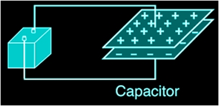
CAPACITORS AND CAPACITANCE
A capacitor is a two-terminal electrical device that possesses the ability to store energy in the form of an electric charge. It consists of two electrical conductors that are separated by a distance. The space between the conductors may be filled by vacuum or with an insulating material known as a dielectric. The ability of the capacitor to store charges is known as capacitance. C =Q/v
THE PARALLEL PLATE CAPACITOR
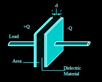
A parallel plate capacitor consists of two large plane parallel conducting plates separated by a small distance We first take the intervening medium between the plates to be vacuum. The effect of a dielectric medium between the plates is discussed in the next section.
![]()
COMBINATION OF CAPACITORS
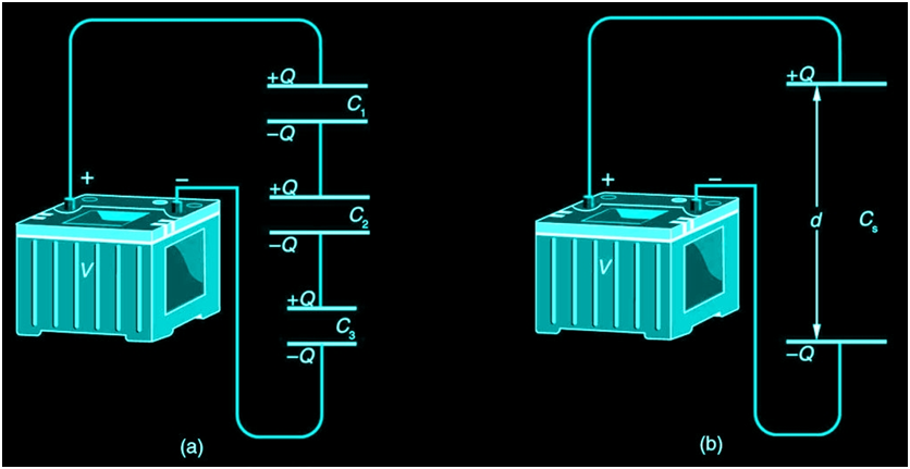
Capacitance in Series
Figure 1a shows a series connection of three capacitors with a voltage applied. As for any capacitor, the capacitance of the combination is related to charge and voltage by C= Q/V
Note in Figure 1 that opposite charges of magnitude Q flow to either side of the originally uncharged combination of capacitors when the voltage V is applied. Conservation of charge requires that equal-magnitude charges be created on the plates of the individual capacitors, since charge is only being separated in these originally neutral devices. The end result is that the combination resembles a single capacitor with an effective plate separation greater than that of the individual capacitors alone. Larger plate separation means smaller capacitance. It is a general feature of series connections of capacitors that the total capacitance is less than any of the individual capacitances.
dividual capacitors Solving C=Q/V for V gives V=Q/C. The voltages across the individual capacitors are thus
V1=Q/C1,V2=Q/C2, and V3=Q/C3.
The total voltage is the sum of the individual voltages:
V = V1 + V2 +V3.
Now, calling the total capacitance CS for series capacitance, consider that
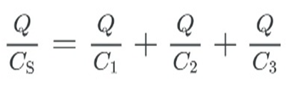
V=Q/Cs =V1+V2+V3.
Entering the expressions for V1, V2, and V3, we get
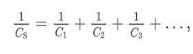
where “…” indicates that the expression is valid for any number of capacitors connected in series. An expression of this form always results in a total capacitance CS that is less than any of the individual capacitances C1, C2, …, as Example 1 illustrates.
Total Capacitance in Series, Cs
Total capacitance in series:
1/CS = 1/C1 + 1/C2 … ..
Capacitors in parallel
Two capacitors arranged in parallel. In this case, the same potential difference is applied across both the capacitors. But the plate charges (±Q1) on capacitor 1 and the plate charges (±Q2) on the capacitor 2 are not necessarily the same:
Q1 = C1V, Q2 = C2V
The equivalent capacitor is one with charge
Q = Q1 + Q2
and potential difference V.
Q = CV = C1V + C2V
The effective capacitance C is, C = C1 + C2
VAN DE GRAAFF GENERATOR
A Van de Graaff generator is an electrostatic generator, invented by Robert J. Van de Graaff. It uses a moving belt that accumulates charge on a hollow metal structure designed like a globe, placed on the top of a column that is insulating in nature and thus, creating a very high electric potential in the order of a few million volts. This results in a very large electric field that is used to accelerate charged particles.
Working principle of Van de Graaff Generator
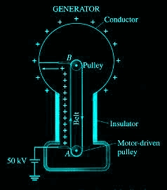
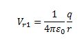
Let us consider a large spherical shell of radius R. If we place a charge of magnitude Q on such a sphere, the charge will spread uniformly over the surface of the sphere and the electric field inside the sphere will be equal to zero, and that outside the sphere will be due to the charge Q placed at the centre of the sphere.
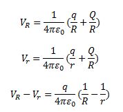
At the surface of the small sphere:
At the large spherical shell of radius R:
If we consider the total charges in the system, that is, q and Q, then the total potential energy due to the system of charges can be given as,