 Madhava Publications
 Grow Career Publication
1. Electric current
- Books Name
- Physics by Anshu Physics Book
- Publication
- Madhava Publications
- Course
- CBSE Class 12
- Subject
- Physics

Introduction
In the previous chapters, we studied the static properties of the electric charges which we call electrostatics. We have seen that charge at rest has various properties like it exerts forces on other charges, produces an electric field around it, and many more.
In this section, we will study the transient properties of the electric charges. What will happen when the charges move?
Moving charges constitute an electric current. Some currents occur naturally in many situations. Lightning is one such phenomenon although it's not steady and it can be dangerous many times when charges flow from the clouds to earth through the atmosphere.
In today's world electricity has become an inseparable part of our lives as most appliances we use run on electricity. But these appliances need a steady source of electric current to function properly. In this section, we will discuss some basic laws concerning the steady electric current.
Electric current
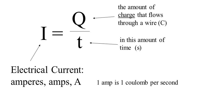
The flow of electric charges constitutes an electric current. Quantitatively, electric current in a conductor across an area held perpendicular to the direction of flow of charge is defined as the amount of charge flowing across that area per unit of time
Now let's understand how we get the above formula.
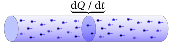
In the figure given below is a conductor in which charges are flowing
And we imagine a small area held normal to the direction of flow of charge like shown in dark purple color in the diagram given below.
Now through this area suppose both positive and negative charge is flowing in the forward direction across the area.
Let q+ be the positive charge flowing forward through the area
And q- be the negative charge flowing forward through the area.
Then the Net charge crossing the chosen small area is q= q+ - q-
This net charge flowing through a small cross-section is actually proportional to ‘t’ for a steady current
The above proportionality can be understood properly with a suitable analogy. Suppose on a national highway, there is a toll plaza. Imagine that the vehicles cross that toll plaza at a steady rate. If you count the number of vehicles crossing the toll plaza for one hour you will get say 100, If you keep counting the vehicles for 10 hours, you will get 1000 vehicles crossing that toll plaza. The more time has elapsed, the number of vehicles passing that toll plaza will be more.
But currents are not always steady and hence more generally, we can define current as I=
Or simply by
Here we have considered
Units of Electric current
S.I. units of electric current is Ampere.
Definition of one ampere
I = Q / t ; when Q=1 C and t= 1s then I = 1 A.
If one coulomb of charge passes through a cross-section in one second, then the current through that area is one ampere (A).
Conventional and electronic current
At the time when this phenomenon of electric current was discovered, electrons had not yet been discovered so it was thought that electric current is due to the flow of positive charges. So the conventional direction of electric current is taken in the direction of the flow of positive charges.
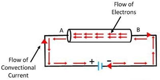
However, a negative charge moving in one direction is equivalent to a positive charge moving in the opposite direction. Later on, electrons were discovered by J. J Thomson and it was later established that electric current in conductors is due to the motion of free electrons. The direction of flow of electrons in a conductor or we can say that electronic current is opposite to the direction of flow of positive charges and hence also opposite to the direction of conventional current.
Electric current : Scalar / vector ?
What do you think? An electric current should be a scalar or vector. Many students can say as the electric current has both direction and magnitude it must be a vector. But this is not correct. Actually, electric current is a scalar quantity.
Even though it has direction, it does not follow vector addition laws. Electric current is a scalar quantity because the laws of ordinary algebra are used to add electric currents and the law of vector addition is not applicable here
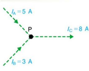
For example, in the figure shown below, we have three wires and three currents. IA= 5 A, IB= 3 A and both are incoming currents toward point P. Ic must be an outgoing current with magnitude = ( IA+ IB = 8 A). current in wire C is calculated via scalar addition and not vector addition laws. So electric current is a scalar quantity.
Electric current in the conductor.
When a charged particle is placed in an electric field, it will experience an electric force on it and will begin to move and this motion of charge will contribute to electric current. Now the question is every matter is made of atoms and in every atom, we have electrons and protons, so does it mean that every matter should conduct electricity when placed in an electric field?
The answer is no!
Let me tell you more precisely that electric current is due to the motion of free charges and not the bound charges. In most matters the electrons and protons in the matter are in a bound state, such matter cannot conduct electricity and are called insulators.
In other materials, notably metals, some of the electrons are practically free to move within the bulk material. These materials are generally called conductors. In solid metals, electricity is conducted by free electrons ( due to the flow of negative charge only). There are some other types of conductors like electrolytes in which conduction is due to ions both positive and negative charged ions.
In this text, we will focus only on metals for conduction.
Now another question arises at any point in time, any metals have a very large number of free charges. So is there always an electric current in the metals? Again the answer would be No! Because if it happens then you could no longer touch any metals. You will get an electric shock if you do so.
The main question is why does it happen?
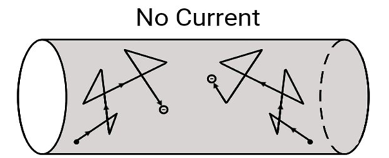
At any time free electrons inside the conductors are in motion due to thermal agitation ( in other words due to thermal energy). In this motion, they collide with each other and also with the fixed ions. Electrons colliding with ions emerge at the same speed as an elastic collision.
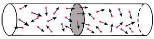
But due to the random motion of the free charges inside the conductor, there is no preferred direction of motion. The number of electrons traveling in any direction will be equal to the number of electrons traveling in the opposite direction. So there will be no net electric current
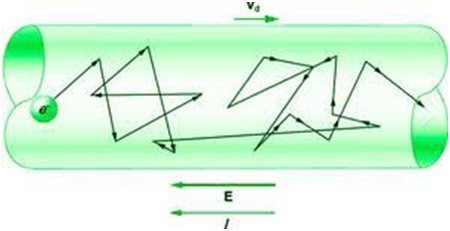
Let us see now what will happen to such a piece of the conductor when we apply an electric field to it. Imagine we have a cylindrical conductor with a uniform circular cross-section. When we apply an electric field at the cross-section. The electrons will experience a force in a direction opposite to the direction of the applied electric field.
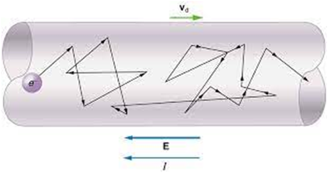
The electrons are accelerated toward the positive terminal, even now it collides with other electrons and ions in its path, but there is a preferred direction of drift of electrons called ‘Vd’ which is opposite to the direction of the applied electric field and current. This is all about Electric current and conductors.
1. Electric current
- Books Name
- Physics Book Part l and ll
- Publication
- Grow Career Publication
- Course
- CBSE Class 12
- Subject
- Physics
Chapter 3: Current Electricity
Current Electricity
Electric current is the flow of electrons through a complete circuit of conductors. It is used to power everything from our lights to our trains.In these activities, students will explore different kinds of circuits and investigate what is required to make a complete circuit.
Types of Current
There are two types of current
1. Direct Current (DC)
2. Alternating Current (AC)
Direct Current
The current electricity whose direction remains the same is known as direct current. Direct current is defined by the constant flow of electrons from a region of high electron density to a region of low electron density.
Alternating Current
The current electricity that is bidirectional and keeps changing the direction of the charge flow is known as alternating current. The electrical outlets at our home and industries are supplied with alternating current.
2. Ohm's Law
- Books Name
- Physics by Anshu Physics Book
- Publication
- Madhava Publications
- Course
- CBSE Class 12
- Subject
- Physics

Introduction :
Ohm’s law is the basic law regarding the flow of current. It was discovered by G.S. Ohm in 1828, long before the physical mechanism responsible for the flow of current - ‘electrons
The electrons were discovered by J.J. Thomson in 1897.
Ohm’s Law
Imagine a conductor through which a current is flowing
Let the V be the potential drop across the conductor. Then Ohm's Law states that
The potential drop across the conductor is directly proportional to the current.
To remove the sign of proportionality we need to put some constant so. V= R I
Here. R= resistance of the conductor.
S.I. unit of resistance = ohm
When current flows through the conductor it feels a resistance to its flow. The resistance of the conductor is independent of voltage or current.

There cannot be a better explanation of ohm’s law than the cartoon given below in the figure.
The figure describes how voltage is trying hard to push the current. And the resistance is trying to constrain the path of the current. We can draw two conclusions from it.
- More the potential difference we apply on the ends of the conductor, the more will be the current passing through that conductor.
- More the resistance of the conductor, the lesser will be the value of current passing through the conductor. Current is inversely proportional to resistance.
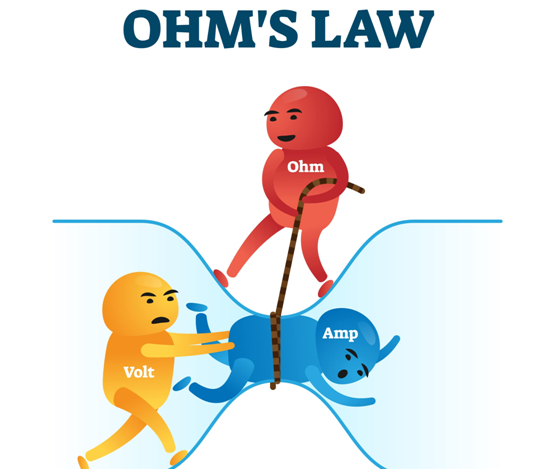
Similarly, you can conclude that V is that factor that supports the current and R is that factor that opposed it

Resistance
The resistance of the conductor depends on
- Length of the conductor
- Area of cross-section
- Nature of material of the conductor.
Now let's try to understand what caused the conductor to offer resistance to the flow of current and why it depends on the factors above. Let's try to get these answers first.
What causes the conductor to offer resistance to the flow of current?
In a conductor there are large numbers of electrons and ions, free electrons moving in the conductor suffer many collisions with the bound electrons, ions and other free electrons. These frequent collisions hinder the flow of electrons and thus provide resistance to the flow of charges and also provide resistance to the flow of electric current.
Why does resistance of conductor depend on the factors mentioned above?
I want to answer this with the help of an analogy. Imagine a very busy road where collisions with other vehicles are very frequent ( just a hypothetical situation ) with hundreds of vehicles on it. The longer that road is, the chance of more collisions. The same analogy is with a conductor, longer the conductor, more will be the number of collisions it would suffer and hence will offer greater resistance to the flow of current.
Resistance of the conductor is directly proportional to the length of the conductor
Now imagine two roads, one is a narrow road and the other will be wider. Suppose the same number of vehicles are traveling on both roads. Now tell me on which road the collisions between vehicles should be less narrow or wider? Obviously, the answer would be that collisions will be lesser on wider roads. You can answer it based on your daily experiences. In the same way, a conductor with a wider cross-section offers less frequent collisions than a conductor with a narrow cross-section
Hence resistance is inversely proportional to the cross-section area.
The third dependence of resistance is on the nature of the material of the conductor. Resistance depends on the charge density of the conductor and also some other factors like mean free path, relaxation time, and mass of the constituent atoms or molecules. These parameters are different for different metals. We account for all these factors in a single quantity called resistivity
Therefore resistance is directly proportional to the resistivity of the conductor.
If we combine all three we will get.
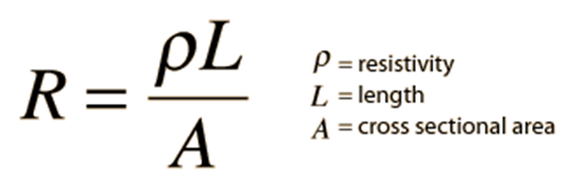
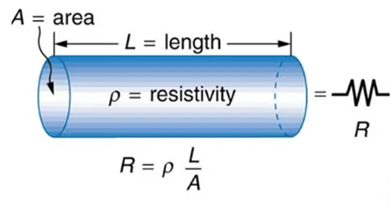
Resistivity: Resistivity or specific resistance of a material may be defined as the resistance of a conductor of that material having a unit length and unit cross-section area. It is denoted by
I- V characteristic and the resistance
I-V characteristic and the resistance are closely related, we can find the resistance of a conductor by using its I-V characteristic.
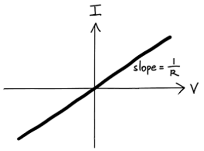
The slope of the I-V characteristic gives 1/R.
V= I*R ; I = (1/R) * V
If we plot current along the y-axis and voltage on X-axis then, Comparing this with the equation of straight line y = m x, we can conclude that the slope of the I-V graph gives ‘ slope m=1/R’, we can find resistance R= 1/slope. refer to the graph above. The greater the slope of the I-V characteristics lesser is the value of resistance.
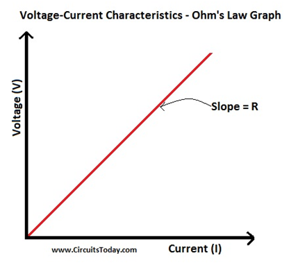
Now if we have a V-I graph, voltage is represented along the y axis and current along the ‘x-axis. Then on comparing the V= R I with y= m x, we can conclude that the slope of the V-I graph is equal to the resistance. Greater the slope of V-I characteristics, the greater the value of resistance.
Current density, conductance and conductivity:
Let us quickly go through these definitions
Current Density: The current density at any point inside a conductor is defined as the amount of charge flowing per second through a unit area held normal to the direction of the flow of charge at that point. It is a vector quantity. Current density j= current/ area perpendicular to the direction of the current.
J= I / A
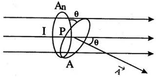
If the area is not perpendicular to area A but makes an angle
Component of Area normal to the current ‘An’= A cos
J= I/ Acos
S.I. Unit = Ampere per square meter. ( A/m^2)
Conductance: The conductance of a conductor is the ease with which electric charges flow through it. It is equal to the reciprocal of resistance. It is denoted by G
Conductance = 1 / resistance
G= 1/ R
S.I unit is mho or siemens (S)
Conductivity: The reciprocal resistivity of a material is called conductivity. It is denoted by
Conductivity = 1 / resistivity
S.I. Unit is siemens per meter. (S/m)
Vector form of ohm’s law.
If E= magnitude of the electric field in a conductor
l= length of the conductor, A= Cross-section area of conductor
V= potential difference,
R= Resistance, J= current density
Then
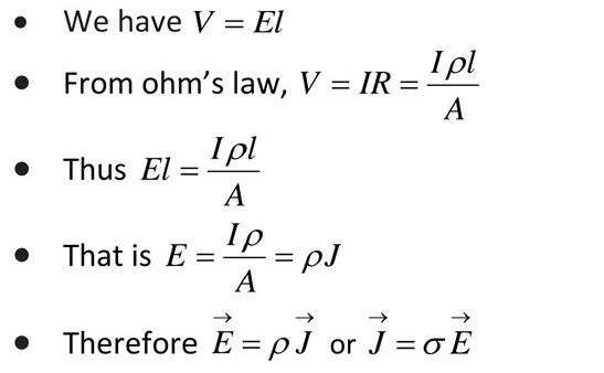
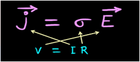
The above expression J=
Limitations of Ohm’s Law
- This law is not applicable to unilateral networks. Unilateral networks allow the current to flow in one direction. Such types of networks allow the current to flow in only one direction.
For example, transistors, diodes etc.
- This law is not applicable for non-linear electrical elements with parameters like capacitance, resistance etc. voltage in such circuits won't be constant with respect.
- Ohm’s law is only applicable for metallic conductors and not valid for non-metallic conductors.
I-V characteristic of various electrical elements.
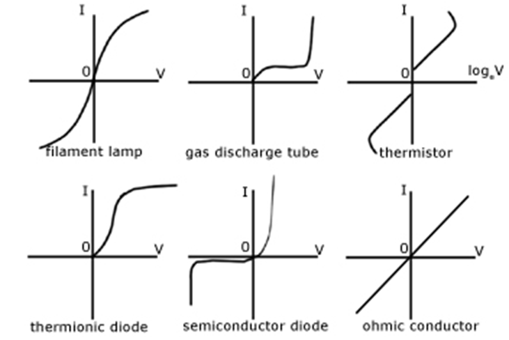
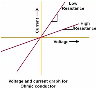
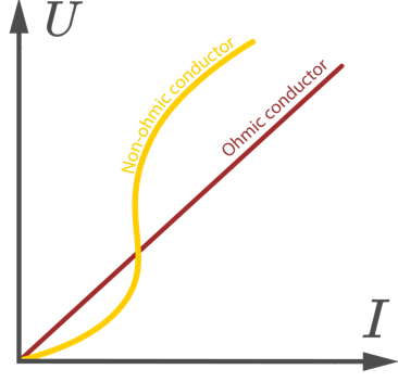
Ohmic and Non-ohmic conductors
In ohmic conductors, the graph between Voltage and current is linear. The graph starts at the origin and is a straight line. These conductors follow ohm’s law. I-V characteristic graphs of non-ohmic conductors are non-linear graphs, usually curved ones.
Note: A straight-line graph with an intercept ( not starting from the origin ) is also a non-linear graph.
Drift velocity, mobility and relaxation time for the conductors
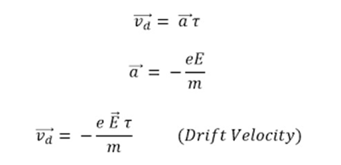
When we apply electric field ‘E’ across the end of the conductors. Free electrons experience a force on it ‘F= -eE’ and thus also experience an acceleration. F= ma= -eE so a = -eE/m, This is the acceleration experienced by the charge in the presence of an electric field.
The electron in the conductor will start to drift in a direction opposite to the direction of the Electric field. But the electrons would still suffer multiple collisions but now there will be a preferred direction of motion of electrons. The average time between two successive collisions of an electron is called relaxation time
The velocity gained during this time is called drift velocity ‘Vd’ Vd= a*
Drift velocity may be defined as the average velocity gained by the free electrons of a conductor in the opposite direction of the externally applied electric field.
Mobility of charge carriers
The conductivity of any material is due to its mobile charge carriers. Greater the mobility of a charge carrier will be its conductivity.
The mobility of a charge carrier is the drift velocity acquired by it in a unit electric field. I
Mobility is denoted by
Expression of current in terms of drift velocity and mobility
We can express an electric current in terms of drift velocity and mobility also.
I= neA *Vd = neA*
Where I= electric current
n= free charge density of the conductor
A= Area of a cross-section of conductor
Vd= drift velocity
E= applied electric field.
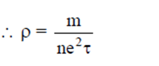
Expression of resistivity in terms of electron density and relaxation time
We can get the resistivity in terms of electron density and relaxation time. We would start with the formula of drift velocity and current in terms of drift velocity. We will then rearrange the terms and use ohm’s law.
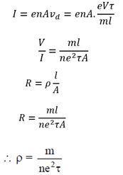
The above expression is the formula for resistivity
It depends on two factors :
- Number of free electrons per unit volume or electron density of the conductor
- The relaxation time
The resistivity of different materials.
The materials are classified as conductors, insulators and semiconductors.
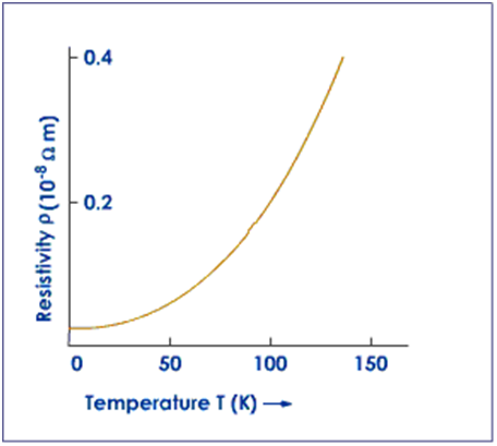
Conductors: The materials which conduct electric currents are conductors. The resistivity of the conductors is very low. It ranges from 10^(-8)
Copper and aluminum have the lowest resistivity. Nichrome has a resistivity of about 60 times that of copper so nichrome is used in electric heaters and electric iron. Metals have a positive coefficient of resistivity. With the increase in the temperature of metals their resistivity increases.
Insulators: The materials which do not conduct electric currents are insulators. They have high resistivity, more than 10^4
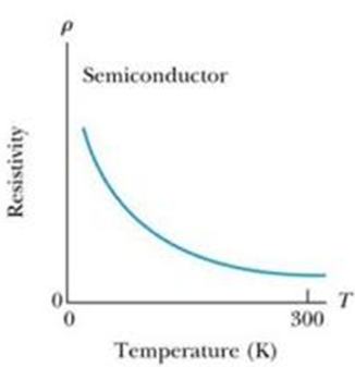
Semiconductors have a negative temperature coefficient of resistivity. The resistivity of semiconductors decreases with an increase in temperature.
Temperature dependence of the resistivity
If we see the formula for resistivity we do not see temperature explicitly present there. Then why does the resistivity depend on temperature?
The answer to this question is that resistivity depends inversely on relaxation time. The relaxation time is the average time elapsed between two successive collisions. This relaxation time actually depends on temperature.
As the temperature increases, there will be more frequent collisions and thus reducing the relaxation time. If you follow the formula for resistivity, you can tell that resistivity is inversely proportional to relaxation time. If the relaxation time would decrease with increase in temperature. Resistivity would increase with increase in temperature.
So. Yes! There is no explicit dependence on temperature in the formula of resistivity, but it is implicitly present during the relaxation time.
In the above text, I have explained why the temperature affects the resistivity of a conductor. Now the next question will be How much does the temperature affect the resistivity of any conductor?
Resistance and resistivity both increase with the increase in temperature in exactly the same manner. As they are Resistance is directly proportional to resistivity. In the figure given below, there is given the formula.
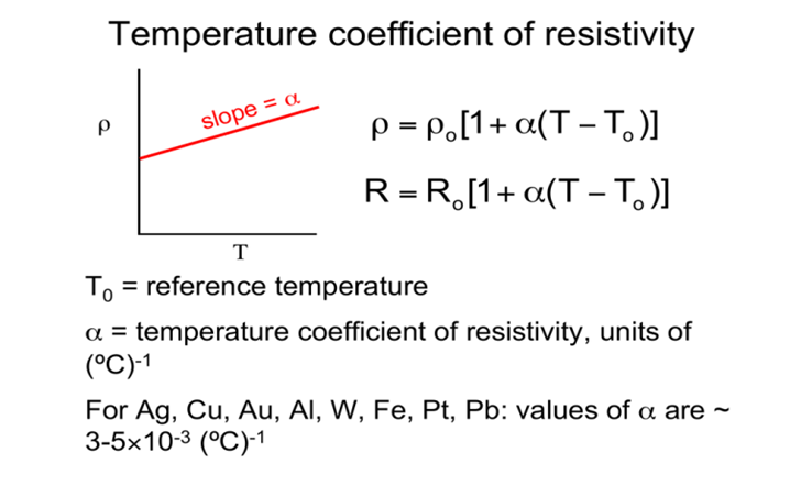
If we consider the dependence of resistance on temperature
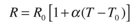
Here R= resistance at temperature T
R0= resistance at temperature To
To= reference temperature is usually 20 degrees Celcius but sometimes it is 0 C.
T= given temperature
Temperature coefficient of resistivity
We can find the temperature coefficient of resistivity by just rearranging the terms. Consider,
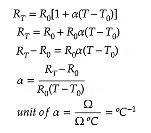
Note: the value of
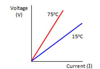
For conductors, the value of resistivity and hence resistance would increase with the increase in temperature. As shown in the figure below. At higher temperatures, the slope of the V-I graph will be more.
Electrical power and energy
To maintain the steady flow of current through the conductor in a circuit an external force is required which must supply the power. In a simple circuit with a cell, It is the chemical energy of the cell which supplies this power. Moreover, Inside the conductor when free charges are drifting inside the conductor under the action of the electric field, their kinetic energy would increase as they move, However, we have got that charges do not move with acceleration but move with steady drift velocity.
This is because of the collision of the ions and the atoms during transit. The kinetic energy gained by the charges is shared by the atoms during collisions and atoms start vibrating vigorously, and the conductor heats up. Thus an amount of energy is dissipated as heat in the conductor. The energy dissipated per unit time is called power dissipated. The formula for the power dissipated is given below.
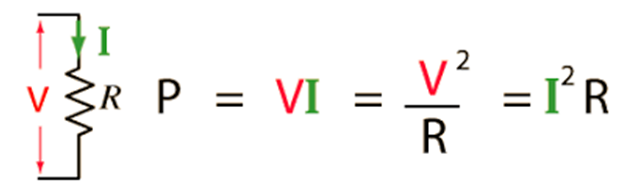
Where R= resistance of the conductor, V= potential difference and I= current through the conductor. If you are someone who always struggles between energy and power. Let me try to help you with that.
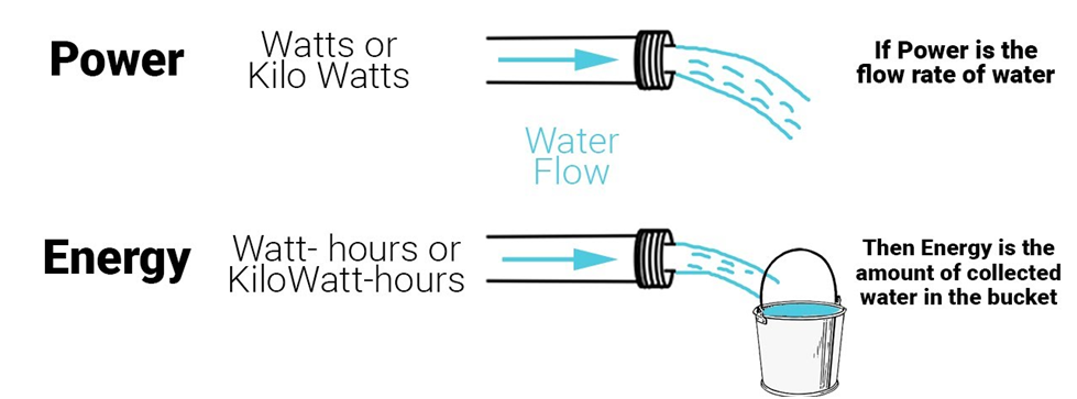
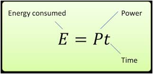
Please look at the diagram above, It relates energy and power with water flowing through a pipe and collecting in the bucket.
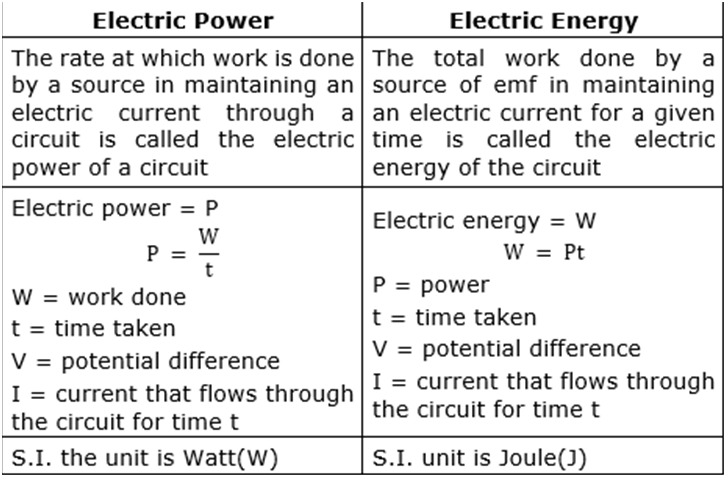
Power is actually the rate of doing work or here it can be related to the rate of flow of water and energy is the amount of work done in some time ‘t’ and here it is related to the amount of water collected in the bucket in time ‘t’. We can conclude the discussion above about electrical energy and power in a table.
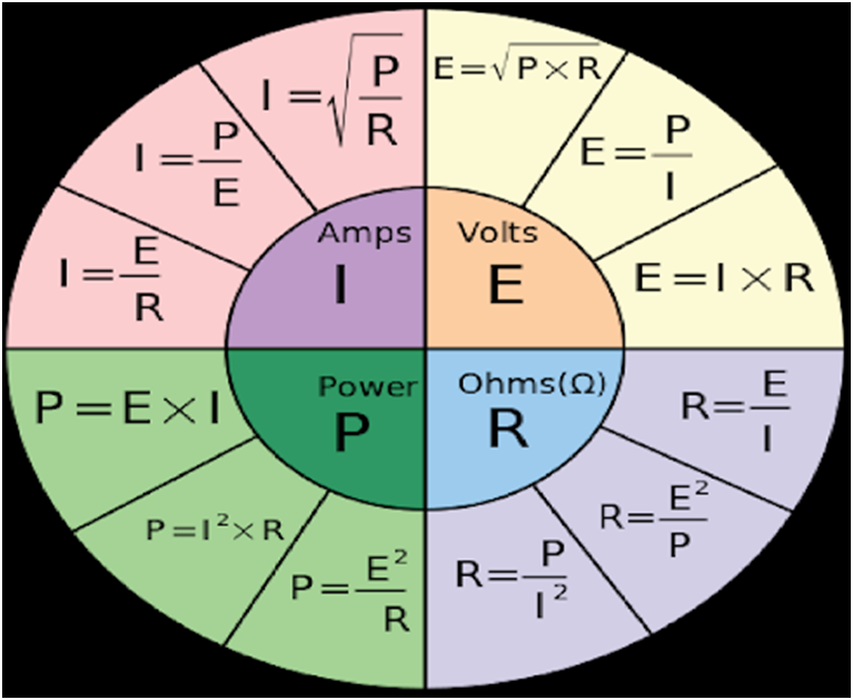
The above diagram can help you to remember all these formulas.
A fun thing to do: Below is the link to the simulation of ohm’s law, you can play with it.
Explanation of the simulation: In this simulation, there is a circuit with some battery and resistor and you can see the values of V, I and R.
What you do in this
- You can change the value of voltage by sliding the voltage up and down can note how current is changing
- You can change the value of resistance in the circuit for a fixed value of V and see how current will be varying.
2. Ohm's Law
- Books Name
- Physics Book Part l and ll
- Publication
- Grow Career Publication
- Course
- CBSE Class 12
- Subject
- Physics
OHM’S LAW
A basic law regarding flow of currents was discovered by G.S. Ohm in.1828,Ohm’s law states that the current through a conductor between two points is directly proportional to the voltage across the two points.
V = IR
LIMITATIONS OF OHM’S LAW
Although Ohm’s law has been found valid over a large class of materials, there do exist materials and devices used in electric circuits where the proportionality of V and I does not hold.
- Ohm’s law is also not applicable to non – linear elements. Non-linear elements are those which do not have current exactly proportional to the applied voltage that means the resistance value of those elements changes for different values of voltage and current. Examples of non – linear elements are the thyristor.
- The relation between V and I depends on the sign of V. In other words, if I is the current for a certain V, then reversing the direction of V keeping its magnitude fixed, does not produce a current of the same magnitude as I in the opposite direction. This happens for example in the case of a diode.
RESISTIVITY OF VARIOUS MATERIALS
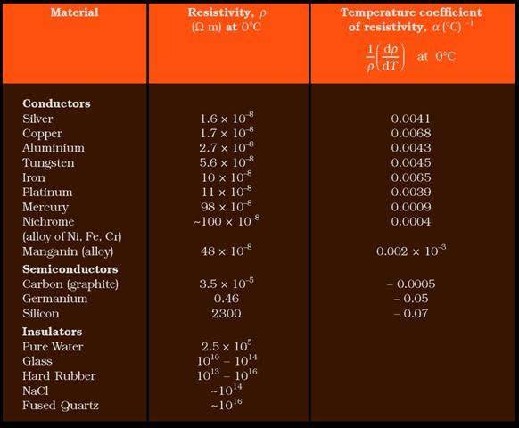
TEMPERATURE DEPENDENCE
The resistivity of a material is found to be dependent on The temperature. Different materials do not exhibit the Same dependence on temperatures. Over a limited range Of temperatures, that is not too large, the resistivity of a Metallic conductor is approximately given by,
ρT = ρ0 [1 + α (T–T0)]
ELECTRICAL ENERGY, POWER
A cell has two terminals – a negative and a positive terminal. The negative terminal has the excess of electrons whereas the positive terminal has a deficiency of electrons. Let us take the positive terminal as A and the electrical potential at A is given by V(A). Similarly, the negative terminal is B and the electrical potential at B is given by V(B). Electric current flows from A to B, and thus V(A) > V (B).The potential difference between A and B is given by
V = V(A) – V(B) > 0
3. Combination of resistors
- Books Name
- Physics by Anshu Physics Book
- Publication
- Madhava Publications
- Course
- CBSE Class 12
- Subject
- Physics
Combination of resistor: Series and parallel
Like we have studied the series and parallel combination of capacitance in electrostatics. Here we will see how we can combine resistors of different resistances in series and parallel and get a value equivalent to resistance in both the cases.
We will be using ohm’s law throughout the topic.
Series combination of Resistors:
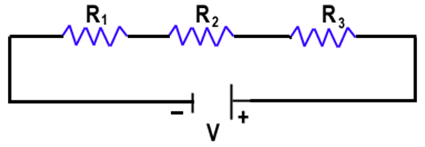
When resistors are joined end to end like in the figure above. We call this combination a series combination of resistors.
In a series combination of the resistances
- The same current passes through all the resistances.
I1=I2=I3=I
- The voltage of the battery gets divided between the resistors, such that the potential difference of the battery V is equal to the sum of individual potential drops of each resistor.
V= V1+ V2+ V3
If we apply ohm’s law we will get,
let Req be the equivalent resistance of the series combination of the resistors
‘I’ be the current in the circuit.
V= potential difference of the terminals of the battery
V1, V2, V3 be the potential drops of R1, R2, R3 respectively
Then from ohm’s Law.
V= V1+ V2+ V3
I * Req= I* R1 + I*R2+ I*R3
Req= R1 + R2+ R3
If we have ‘n’ number of resistors in series then equivalent resistance will be given as:

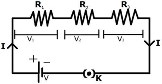
In the circuit given below if we need to find the potential drops through each resistor in series

V1 = Potential drop of R1 = I* R1
Similarly, V2= I*R2 and V3= I*R3
And power dissipated in each resistor,
P1= power dissipated in resistor R1= V1*I = V1^2/R1= I^2*R1
Similarly, we can find the power dissipated by R2 and R3.
Parallel combination of resistors
Below is the figure of the parallel combination of resistors.
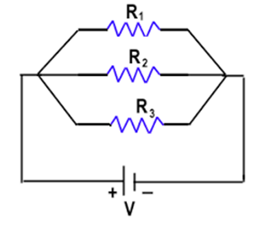
Two or more resistors are said to be in parallel if one end of all the resistors are joined together and similarly the other ends join together.
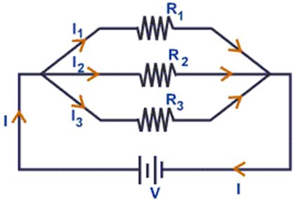
In parallel combination of the resistors
- Voltage is the same across all the resistors connected in parallel and is equal to the potential difference of the battery.
V1= V2= V3=V
- In a parallel combination of resistors, the current is divided between the resistors such that the sum of currents through all the resistors are equal to the total current in the circuit.
I= I1+I2+ I3
Let Req= equivalent resistance of the circuit.
I= total current in the circuit
V= potential difference of the terminals of the battery
I1. I2 and I3 are the currents through R1, R2, and R3 respectively.
By using ohm's law we have
I1= V/ R1 , I2= V/R2 , I3= V/R3 and I= V/Req
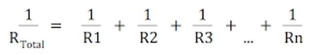
If we put above values in I= I1 + I2 + I3
We will get 1/Req = 1/R1 + 1/R2 + 1/R3, This is the formula for finding equivalent resistance for the parallel combination of the resistors.
If we have two resistors in parallel shown below
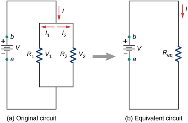
Then equivalent resistance of the circuit will be given by
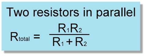
If we have ‘n’ resistors connected in parallel the equivalent resistance will be
Cells, EMF, and Internal resistance
In the circuit given below a positive charge flows spontaneously in a conductor from higher potential to lower potential in the direction of the electric field. To maintain the current through the conductor, some external devices must do some work at a steady rate to take the positive charge from lower potential to higher potential. Such a device is the source of EMF ( electromotive force). These devices can be a battery, cell, or electrolytic solution.
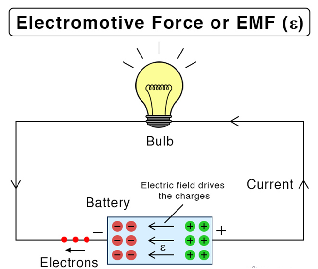
Electromotive force may be defined as the work done by the source in taking a unit positive charge from lower potential to higher potential. The EMF of a source is equal to the maximum potential difference between its terminals when it is in an open circuit. In other words, the emf of a source may be defined as the energy supplied by the source in taking a unit positive charge once round the complete circuit.
The term EMF- electromotive force is actually a misnomer. The emf is not a force at all. It is a special case of potential difference in which the circuit is open.
V= W/q, therefore emf has also the nature of work done per unit charge.
S.I. unit of EMF is Volt.
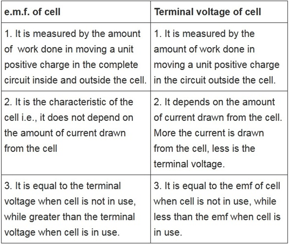
Before going ahead with the topic, Let's have a pause and first try to understand the difference between the EMF of a cell and the potential difference of the cell.
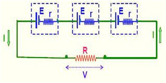
Relation between EMF, Internal resistance and terminal potential difference of the cell
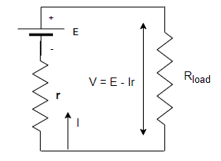
In the circuit, above we have a cell with EMF ‘E’ and internal resistance ‘r’ and it is connected with a load resistance ‘R’in series.
V= potential difference across the load resistance
Total resistance in the circuit= R+ r
Current I= E/(R+r)
So V (terminal potential difference ) = I*R = ER/(R+r)
Also by simplifying we get V= E- Ir
E= V+ I*r = I*R+ I*r = I( R+r)
Special Case:
- When the cell is open I=0 we have V open= E
Thus the potential difference across the terminals of the cell is equal to its emf when no current is being drawn from the cell.
- A real cell has always some internal resistance ‘r’, so when the current is being drawn from the cell, we have
V closed < E
Thus the potential difference across the terminal of a cell in a closed circuit is always less than its EMF
Combination of cells in series and parallel
Like capacitors and resistors, we can also group cells together in series and parallel combinations
Series combination of cells
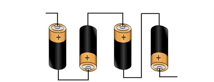
The above combination is the series combination of the cell, where the positive terminal of one cell is connected with the negative terminal of the other cell.
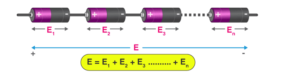
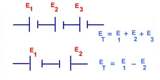
Then the total emf of the cell will be given by some of the emf of all the individual cells.
Suppose we have practical cells with internal resistance as shown in the figure below.
Then equivalent EMF ‘Eeq’ = E1 + E2 +E3
And total internal resistance req= r1+ r2+ r3
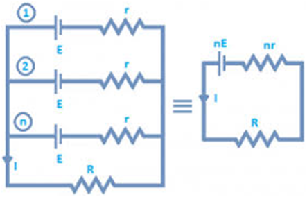
Here all the cells are identical having the same EMF and internal resistance
Eeq= 3E and req= 3r
Therefore, for a combination of ‘n’ identical cells in series
Eeq= nE, equivalent emf will be ‘n’ times the emf of single-cell
req= nr, and equivalent internal resistance would be ‘n’ times the internal resistance of a single cell.
Also, take care of one more concept. If any one of the cells is connected in reverse, then we will subtract the emf of that cell.
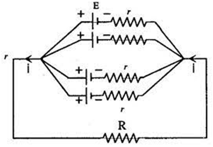
Combination of cells in parallel.
Below is the parallel connection of cells
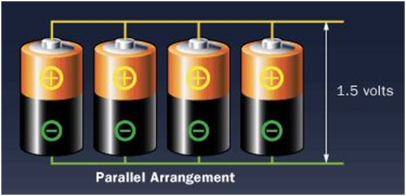
Here all the positive terminals of cells are joined together and similarly, the negative terminals are joined together.
Suppose we have two cells with emf

For parallel combinations of ‘n’ cells, equivalent emf and internal resistance is given by following relations.
A fun thing to do:
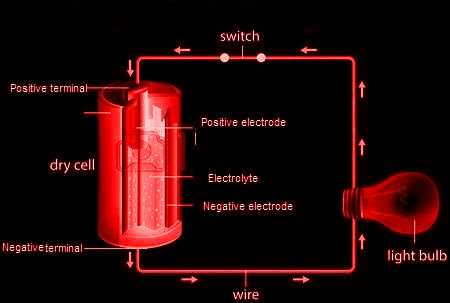
Below is the link to a simulation with which you can design your own circuits using various electrical elements like wire, batter, light bulb, resistor of different values, switch, fuse etc. Just as many circuits as you want and learn with fun.
What can you get from this?
- It can show the direction of conventional and electronic current
- Using voltmeter and ammeter in your circuit you can get the value of voltage and current.
- There is some advanced tools also that can change the wire resistivity and also the battery internal resistance
3. Combination of resistors
- Books Name
- Physics Book Part l and ll
- Publication
- Grow Career Publication
- Course
- CBSE Class 12
- Subject
- Physics
COMBINATION OF RESISTORS
SERIES AND PARALLEL
The connection is in such a manner that the current flowing through the 1st register has to then flow further through the 2nd register and then through 3rd. Therefore, a common current is flowing in connection with a resistor in series. At all point in the circuit, the current amoung the resistors is same. For example,
I1 = I2 = I3 = It = 2ma
All the resistors in series that is R1, R2, R3 have current I1, I2, I3 respectively and the current of the circuit is It.
Resistor in Parallel
Unlike, series connection, in parallel connection, current can have multiple paths to flow through the circuit, hence parallel connection is also current dividers. Common voltage drop is across the parallelly connected circuits/networks. At the terminals of the circuit, the voltage drop is always the same. For example
VR1=VR2=VR3=VRT=14V
![]()
The voltage across R1 is equal to the voltage across R2 and similarly, equal to R3 and hence the total voltage drop is equal to the voltage across the circuit. Reciprocal of individual resistance of each resistor and the sum of all the reciprocated resistance of resistor will us the total resistance of the circuit.
CELLS, EMF, INTERNAL RESISTANCE
What is an Electromotive Force (EMF) of a Cell?
The electrolyte has the same potential (emf) throughout the cell. The condition of no current flowing through a cell is also known as an open circuit. An open circuit result in a potential (emf) of the cell is equal to the difference of potentials (emf) of the electrodes. Anode has a positive potential (V+) whereas Cathode has a negative potential (-V–). This potential difference is known as the Electromotive Force (EMF).An electric battery is a device made up of two or more cells that make use of the chemical energy stored in the chemicals and converts it into electrical energy.
4. Law's and Bridge
- Books Name
- Physics by Anshu Physics Book
- Publication
- Madhava Publications
- Course
- CBSE Class 12
- Subject
- Physics
INTRODUCTION:
In 1942, a German Physicist Kirchhoff extended Ohm’s law to complicated circuits and gave two laws, which enable us to determine the current in any part of a complicated circuit easily in an organized way. But before jumping to the topic, let me first introduce some terms that may be used in later topics.
- Electrical network: The term electric network is used for a complicated system of electrical conductors. The above circuit is an electrical circuit.
- Junction: Any point in an electrical circuit where two or more conductors are joined together is a junction. In above circuit b, e are junctions.
- Loop and Mesh: Any closed conducting path in an electric network is called a loop or mesh. In the above circuit, we have two loops, loop abefa and ebcde.
- Branch: A branch is any part of a network that lies between two junctions. In the above circuit ab, bc, cd etc are branches
Kirchhoff’s Law - When we have complicated circuits and use of ohm’s law and formulae for series and parallel connection of resistors to solve the circuit are not very helpful. Kirchoff’s law became the savior for such circuits.
There are two laws of Kirchoff's
- Kirchhoff's Voltage Law (KVL) also called the loop law
- Kirchhoff’s Current Law ( KCL ) also called junction law
Kirchhoff’s Current law ( KCL) - Kirchhoff’s current law states that in an electric circuit, the algebraic sum of current at any junction is zero.
The Sum of currents entering a junction is equal to the sum of currents leaving that junction.
Mathematically, this law can be explained by
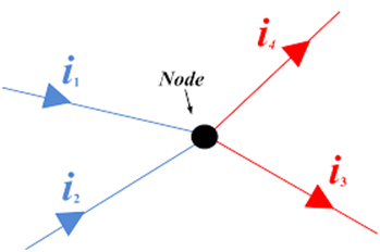
Here you can see that currents in blue colors‘ i1 ‘ and ‘i2’ are incoming currents and currents in the red colors ‘i3’ and ‘i4’ are outgoing
Currents.
So according to KCL, i1 + i2= i3+ i4
Let's see some other examples and try to learn from them.
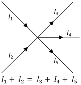
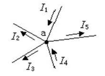
here , I1+ I4= I2 + I3+ I5
I hope with the above examples you have got a better understanding of Kirchhoff's Current Law.
You can also imagine a pipe in which water is flowing, Just like at any place inside the pipe the amount of water coming will be the amount of water going and there is not anything like pilling of water happening inside it. It's just flowing.
In the same way, when charges move inside a conductor, we expect the same ‘ no pilling of charge happens at any point in the circuit’. This is actually the cause of Kirchhoff's current law.
Kirchhoff’s Voltage Law ( KVL) - Kirchhoff’s Voltage Law states that around any closed loop of a network. The algebraic sum of the change in the potential must be zero.
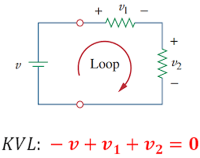
In another word, The Algebraic sum of the emfs in any loop of a circuit is equal to the product of currents and resistances in it.
Mathematically,
The sign convention used in Loop Law ( KVL)
We have to assign a loop current for every loop, we can take any direction as the direction of traversal.
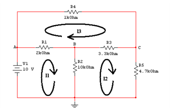
Like in the circuit given below, we have three loops and hence three-loop currents. The direction of all the loops is taken clockwise in the figure given below. The direction of the loop can be anything
- All loops in a clockwise direction
- All loop in an anticlockwise direction
- Some in clockwise and some in an anticlockwise direction.
Like in the circuit given below, we have three loops and hence three-loop currents. The direction of all the loops is taken clockwise in the figure given below.
In the figure given below, the direction of the loop in loop 1 is clockwise and the direction of the loop is anticlockwise in the second loop.
- The emf of the cell is taken to be positive if the direction of traversal is from the negative to positive terminal ( rise in potential ).
- Emf would be taken negatively if the direction of traversal is from positive to negative.
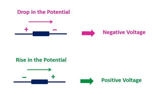
- The current-resistance product ( IR) is taken to be positive if the resistor is traversed in the same direction of the assumed current. ( loop current)
- IR would be negative if the resistor is traversed in the opposite direction of the assumed current.
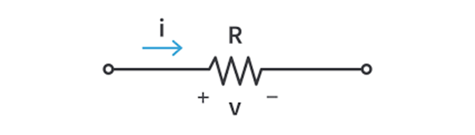
In the above figure if the direction of traversal is the same as the current ( Left to right ) then V= IR would be positive and if the direction of traversal is opposite to assumed current “I” then V= -IR.
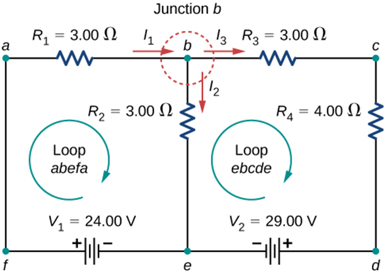
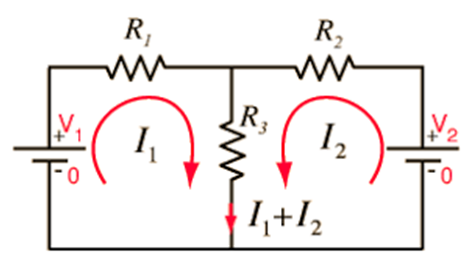
Example - Let's take an example of an electric circuit with two loops. We will apply the above information and try to form the two-loop equations.
In the figure given below, we have two loops. Let's assume that the direction of both loops is clockwise with loop current I1 and I2 respectively.

Let's start to move in loop one abefa in the direction of the loop with loop current I1,
- In the branch, ‘ab’ potential drop across R1 would be written as + I1 *R1 as we are moving along the assumed current I1.
- In the branch ‘be’’, we encounter resistance R2. The potential drop across R2 = + I2*R2 as we are moving along the assumed current I2 in this branch.
- Now in the branch ‘ef’, we encounter an emf source and we are moving from its negative terminal to a positive terminal ( rise in potential so emf would be taken positive( + V1). In branch ‘fa’ there is nothing so leave it.
Now if we use all the above information in the equation
Then we will have + V1= +I1*R1 + I2*R2 as the equation of first loop + 24 = 3* I1+ 3* I2 ………(1)
Let's move to the second loop ‘bcdec’, notice that the current in-branch bc, cd, de is I3 and current in-branch be is I2.
- As we move in-branch bc, voltage drop through R3 will be +I3*R3 and in-branch cd, Voltage drop through R4 will be + I3*R4, as in both the branches we are moving along the assumed current I3.
So the equation for branch bcd will be I3*R3 + I3*R4.
- Now in branch ‘de’ we encounter a battery V2, and while moving from d to e, we are going from the positive terminal of the battery to the negative terminal ( drop-in potential) hence emf would be taken as negative ( -V2).
- In branch ‘eb’ we are going from e to b, but current I2 ( b to e) is opposite to the direction of traversal, So the voltage across R2 in loop 2 will be -I2*R2
If we now combine all information in the equation
We will get -V2 = I3*R3 + I3*R4 -I2*R2
Or , -29 = I3* 3 + I3* 4 - I2*3 = I3 ( 3+ 4) -I2*3
-29= 7*I3 - 3*I2 ………..(2)
Since we have three variables I1, I2, and I3 so we must have 3 equations to solve these variables, we have already got 2 equations.
We can get the third equation by applying KCL at junction b.
At Junction b, I1= I2 + I3 ……. (3)
So, now you can use these three equations and solve for three currents I1, I2, I3 and then you would be able to tell the value of current, voltage drop and direction of current through each resistor.
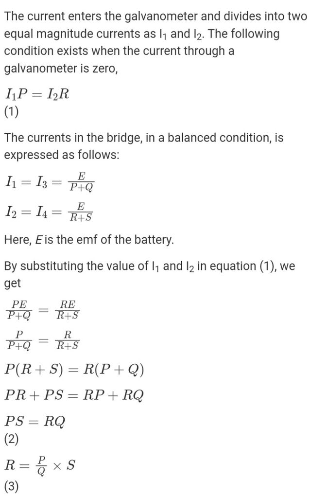
Wheatstone Bridge - Wheatstone bridge is an application of Kirchhoff’s Law.
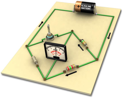
This bridge consists of 4 resistance P, Q, R and S and across one pair of diagonally opposite points ( say AC), a source E is connected. For simplicity, we assume that the internal resistance of the source is zero. And between the other two vertices ( BD) a galvanometer G ( a device to detect current ) is connected. Let G be the resistance of the galvanometer and Ig current passes through it
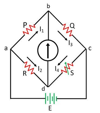
Current I1, I2, I3, and I4 flow through resistors P, R, Q and S respectively, and Ig is the current through the galvanometer.
We can change the resistance of S. There will be one special situation when the galvanometer will show zero deflection and current through it Ig=0. This is called the balanced condition of the galvanometer.
We can use the Kirchhoff laws and use Ig= 0 in that, when we do that we will have a special result about values of resistances P, Q, R and S.
When P / Q = R / S ,
The Wheatstone bridge will be balanced and Ig=0, no current will pass through the diagonal branch and the galvanometer will show no deflection.
Application of Wheatstone bridge - Wheatstone bridge and its balance condition provide a practical method of finding the unknown resistance.
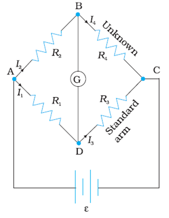
Here resistance R4 is unknown, When we put known resistances R1 and R2 in their places as shown and R3 here is standard resistance whose value can be varied. We go on varying R3 till the galvanometer shows a null deflection and the Wheatstone bridge is in balanced condition.
The resistance of R3 at that time is noted and we can use the condition of a balanced Wheatstone bridge to find the resistance of R4.
R4= R3 ( R2/R1).
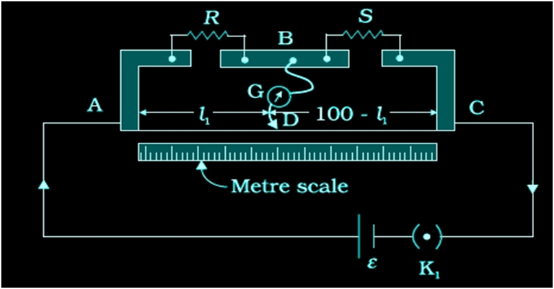
Meter bridge - Meter bridge works on the principle of Wheatstone bridge. But the difference is that the two resistances R1 and R2 in the Wheatstone bridge are replaced by a wire of uniform cross-section and of length one meter. That’s why it is called the Meter bridge.
This wire is stretched tight and clamped between two thick metallic strips bent at right angles.
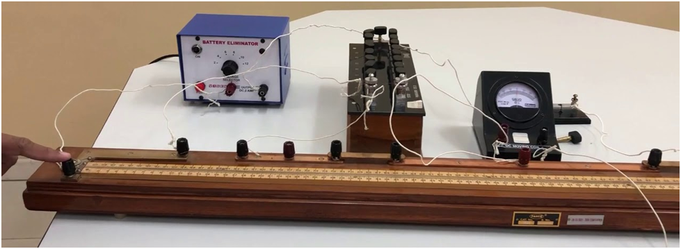
The metallic strips have two gaps ( G1 and G2) across which the two resistors ( P, Q) can be connected. The endpoints ( A and B) where the wire is clamped are connected to a cell through a key.
One end of the galvanometer is connected with the metallic strip midway in between the two gaps( point E). The other end of the galvanometer is connected with the jockey ( J)
A jockey is essentially a metallic rod whose one end is a knife-edge that can slide over the wire of a meter bridge to maintain an electrical connection.
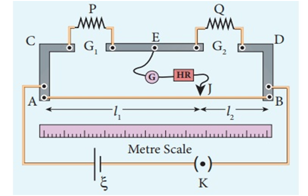
Suppose P is an unknown resistance and Q is known resistance. When we slide the jockey on the wire. On a particular point of the wire, the galvanometer will show null deflection and the meter bridge is in a balanced condition.
Let ‘L1’ be the length of the wire from A to the null point on the wire.
And L2 is the length of wire from B to the null point of the wire.
We know L1 + L2= 1 m = 100 cm
So L2= 100- L1
The four resistance of the bridge in balanced conditions are P, Q, RcmL1 and Rcm(100-L1), where Rcm is the resistance of wire per unit cm.
So, according to the principle of the Wheatstone bridge
P/Q= Rcm*L1 / ( Rcm*(100-L1)
Therefore, P/Q= L1/(100-L1)
So unknown resistance P= Q * L1/ (100-L1)
Where L1 = balanced length of wire from A in cm.
Potentiometer - This is an ideal voltmeter that does not change the original potential difference and still can measure potential difference and also doesn't need to have infinite resistance.
Construction: It is basically a long piece of uniform wire sometimes a few meters in length across which a standard cell is connected. Usually 1 m long wires are fixed on a wooden board parallel to each other. These wires are joined in series by thick copper trips. Then ends of the wire are connected with a battery, a key K and a rheostat. This circuit is called a driving circuit that sends a constant current I through the wire AB. Thus potential difference gradually falls from A to B. A jockey can slide along the length of the wire.
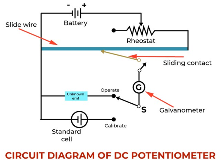
The principle “ When a constant current flows through a wire of uniform cross-section area and composition, the potential drop across any length of the wire is directly proportional to that length.
Where K= proportionality constant called potential gradient.
By ohms law we have
By comparing equations 1 and 2 we can conclude that
Potential gradient -The potential drop per unit length of a potentiometer wire is called the potential gradient.
S.I unit is V/m but the practical unit is V/cm
Sensitivity of the potentiometer is its capability of measuring a very small potential difference and shows a significant change in balancing length for a small change in the potential difference is measured.
How we can increase the sensitivity of the potentiometer:
- For a given potential difference sensitivity can be increased by increasing the length of the potentiometer wire
- For a potentiometer wire of fixed length, the potential gradient can be decreased by reducing the current in the circuit with the help of a rheostat.
Application of potentiometer
1 . comparison of emf’s of two primary cells.
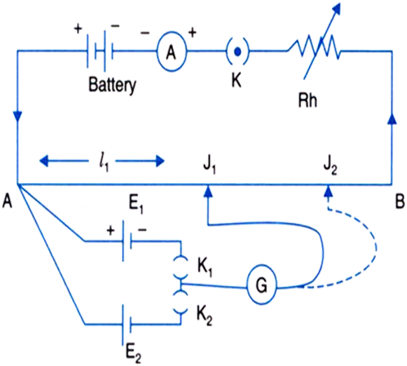
For the comparison of the emf’s of the two cells, the circuit above will be used. Here E1 and E2 are the emf’s of the two cells. Suppose when key K1 is closed and K2 is open and jockey J is moved on the wire AB, the balancing length corresponding to E1 will be ‘L1’.
Now when K2 is closed and K1 is open, the balancing length corresponding to cell E2 is ‘L2’.
From 1 and 2 we have
If emf of one cell is known and emf of another cell is known then we can find the unknown emf of the cell.
2. To find the internal resistance of the primary cell
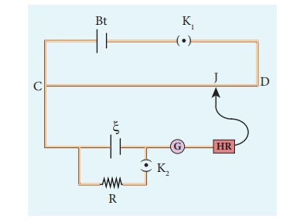
Using the above circuit we can find the internal resistance of the cell.
Close the K1 and keep the Key 2 open and move the jockey on the potentiometer wire. Suppose you get balancing length ‘L1’ corresponding to the emf of cell E
Now close both key K1 and k2 and move the jockey on the potentiometer wire and let you get a balancing length ‘L2’ corresponding to potential drop V
From 1 and 2
From Ohm’s law, we know that
Comparing 3 and 4 we get
Therefore
Equation 5 is used to find the internal resistance of the cell using a potentiometer.
4. Law's and Bridge
- Books Name
- Physics Book Part l and ll
- Publication
- Grow Career Publication
- Course
- CBSE Class 12
- Subject
- Physics
KIRCHHOFF’S RULES
Electric circuits generally consist of a number of resistors and cells interconnected sometimes in a complicated way. The formulae we have derived earlier for series and parallel combinations of resistors are not
Mvalways sufficient to determine all the currents and potential differences in the circuit. Two rules, called Kirchhoff’s rules, are very useful for analysis of electric circuits.
V = ε + I r
WHEATSTONE BRIDGE
The Wheatstone bridge works on the principle of null deflection, i.e. the ratio of their resistances are equal and no current flows through the circuit. Under normal conditions, the bridge is in the unbalanced condition where current flows through the galvanometer.
METER BRIDGE
A meter bridge consists of a wire of length 1 m and of uniform cross-sectional area stretched taut and clamped between two thick metallic strips bent at right angles with two gaps across which resistors are to be connected. The end points where the wire is clamped are connected to a cell through a key. One end of a galvanometer is connected to the metallic strip midway between the two gaps. The other end of the galvanometer is connected to a jockey which moves along the wire to make electrical connection.

POTENTIOMETER
This is a versatile instrument. It is basically a long piece of uniform wire, Sometimes a few meters in length across which a standard cell is Connected. In actual design, the wire is sometimes cut in several pieces Placed side by side and connected at the ends by thick metal strip.