 Grow Career Publication
 Madhava Publications
- Books Name
- Physics Book Part l and ll
- Publication
- Grow Career Publication
- Course
- CBSE Class 12
- Subject
- Physics
Chapter 6: Electromagnetic Induction
Magnetic flux
Magnetic flux is a measurement of the total magnetic field which passes through a given area. It is a useful tool for helping describe the effects of the magnetic force on something occupying a given area.
If we choose a simple flat surface with area A as our test area and there is an angle θ between the normal to the surface and a magnetic field vector (magnitude B) then the magnetic flux is
Φ=BAcosθ
- Books Name
- Physics by Anshu Physics Book
- Publication
- Madhava Publications
- Course
- CBSE Class 12
- Subject
- Physics
Introduction
We have studied electrostatics and magnetostatics in previous chapters as two different phenomena. But later on, it was discovered that they are not two different phenomena. These are like two faces of the same coin. They are not independent but linked to each other under a wider category of interaction which is called electromagnetic interactions. Electromagnetic interactions are one of the four fundamental interactions of the universe.
In this unit, we will see that changing magnetic fields also produce emf and hence electric current.This phenomenon is called electromagnetic induction. We will discuss such phenomena in detail in this chapter.
Experiment of Faraday and Henry
Discovery of electromagnetic induction is based on a series of experiments carried out by Faraday and Henry. The theoretical explanation of the experiment was later given by Faraday and Lenz which are known as the laws of electromagnetic induction.
Note for the student: In the following experiments along with the observation, I have given the explanation of the observation too in blue color and used the word magnetic flux many times in that explanation which I have not discussed before. Students can read about the magnetic flux in the latter topic.
Experiment 1: A coil and a magnet
Consider a loop of wire, connected with a galvanometer and a bar magnet as shown in the figure. We will keep the wire loop fixed in place and the bar magnet can be moved back and forth as shown in the figure.
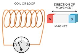
- Initially, when the magnet is far from the coil, there is no deflection in the coil, This is because no magnetic flux will be linked with the coil and hence the deflection of the galvanometer is zero.
- As the coil is moved near the coil, magnetic field lines will be linked with the coil and these field lines will change as the coil continues to move and the galvanometer will show deflection.
- Suppose as in figure ‘b’, a magnet is placed inside the coil and it is kept stationary, there will be no deflection in the galvanometer.
This happens because the magnetic flux linked with the coil is constant and does not change with time
Again like in figure ‘c’, if we now try to move the magnet away from the coil, we will again see that the galvanometer shows deflection but now in the opposite direction. Here magnetic flux
- linked with the coil is also changing, it is decreasing as the magnet is moving away from it.
- Now like in the figure ‘d’, if we keep the magnet at rest outside the coil, the galvanometer will show no deflection
This happens as the magnetic flux linked with the coil is constant when there is no relative motion between the coil and the magnet
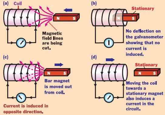
- If we now keep the magnet stationary and move the coil near the magnet, we will again observe that the galvanometer will show deflection like before.
- Deflection was found larger when we move the magnet faster near the coil keeping the coil fixed or moving the coil near the fixed magnet.
Conclusion: The results from the above experiment show that It is the relative motion between the magnet and the coil which is responsible for the generation ( induction ) of electric current in the coil.
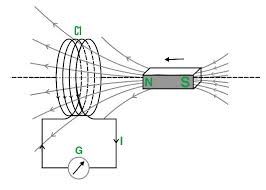
Experiment 2: One coil with a galvanometer and another coil connected with a battery.
We have two coils C1 and C2. Coil C1 is connected with a galvanometer and coil C2 is connected with a battery source that produces a constant current.
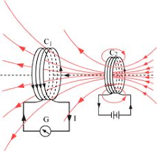
- Keep C1 fixed and move C2 toward C1, the galvanometer will show deflection. Now if we move coil C2 away from coil C1, again the deflection will produce in the galvanometer. Hence there will be an induced current in coil C1.
- Keep C2 fixed and move C1 toward C2, the galvanometer will show deflection. Now if we move coil C1 away from coil C2, again the deflection will produce in the coil. Hence there will be an induced current in coil C1.
Conclusion: Again it is the relative motion between the coils that induce the electric current
Experiment 3: Both coils are kept stationary
In this experiment, we have two coils C1 and C2. Coil C1 is connected with the galvanometer and C2 is connected with a battery and key k.
- When the key of the circuit is closed, there is a momentary deflection in the galvanometer
Explanation is that when the key is open, there would be no current in C2 and hence the magnetic field would also be zero. So there will be no magnetic flux linked with the coil, but when the switch is closed, there will be a sudden increase in current in Coil C2 and magnetic flux linked with C1 suddenly changes so there is momentarily deflection in the coil.
- There is no deflection in the galvanometer after the key of C2 is closed.
Explanation is that when there is a steady current in C2 and hence magnetic field produced by the C2 is also constant. So the magnetic flux linked with coil C1 will also remain the same and hence no current will be produced in C1 and hence the galvanometer shows zero deflection.
- When the key is opened again, there will be again momentarily deflection in the coil.
Explanation is that when the key is opened, the current in Coil C2 changes from a steady value to zero and hence produces a changing magnetic field. The magnetic flux linked with the coil also changes from a finite value to zero. And hence there is a momentarily induced current in the coil C1 and hence the galvanometer shows momentarily deflection.
Magnetic flux
There was a need for a mathematical tool to explain the series of experiments carried out by Faraday on electromagnetic induction.
So he defined the notion of magnetic flux ‘
The magnetic flux through any surface placed in a magnetic field is the total number of magnetic lines of force crossing this surface normally.
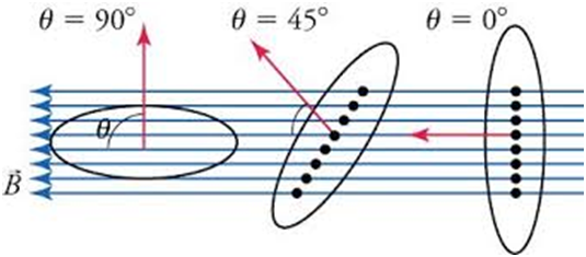
Magnetic flux would be maximum when
Magnetic flux will be zero when
Dimension of
In S.I. The unit of magnetic flux is Weber.
One weber is the flux when a uniform magnetic field of one tesla acts normally over an area of
S.I. unit is Weber and in C.G.S. The unit is maxwell.
How can magnetic flux links be changed?
Mathematically magnetic flux is equal to
So there are following ways to change the magnetic flux
- By changing the magnetic field
- By changing the area of the loop or closed circuit
- By changing the orientation of the closed circuit with respect to Magnetic flux.
We can either do one of the above-mentioned ways to change the magnetic flux or we can do more than one change simultaneously.
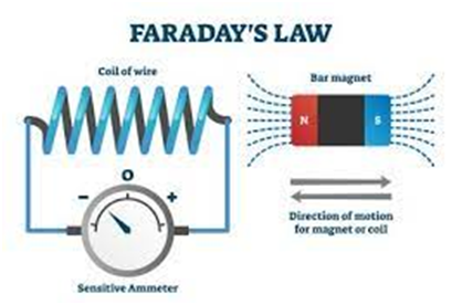
The Faraday Law of Induction
In the experiment discussed above, we have following observation that
- When there is a relative motion between the coil and the source of the magnetic field, an electric current is induced in the coil.
- The common point in all observations is that more deflection is produced when the magnet is moved rapidly near the coil.
Now we will use the concept of magnetic flux to explain how this happens.
Faraday explained that whenever there is relative motion between the coil and the magnet or a source of magnetic field ( current-carrying coil), the magnetic flux linked with the coil changes and thus an emf is induced in the coil and hence there is an induced electric current in the coil. He also noticed that in every experiment, emf induced is directly proportional to the rate of change of magnetic flux in the coil.
Faraday’s Law of Electromagnetic induction:
- Whenever the magnetic flux linked with a closed circuit changes, an emf (and hence a current) is induced in it which lasts only so long as the change in flux is taking place. This phenomenon is called electromagnetic induction.
- The magnitude of the induced emf is equal to the rate of change of magnetic flux linked with the closed circuit.
Mathematically,
For the N turn of the coil
Thus induced current emf can be increased by increasing the number of turns N of a closed coil.