 Madhava Publications
 Grow Career Publication
- Books Name
- Physics by Anshu Physics Book
- Publication
- Madhava Publications
- Course
- CBSE Class 12
- Subject
- Physics
Combination of resistor: Series and parallel
Like we have studied the series and parallel combination of capacitance in electrostatics. Here we will see how we can combine resistors of different resistances in series and parallel and get a value equivalent to resistance in both the cases.
We will be using ohm’s law throughout the topic.
Series combination of Resistors:
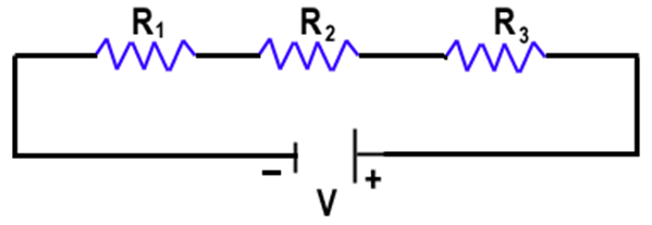
When resistors are joined end to end like in the figure above. We call this combination a series combination of resistors.
In a series combination of the resistances
- The same current passes through all the resistances.
I1=I2=I3=I
- The voltage of the battery gets divided between the resistors, such that the potential difference of the battery V is equal to the sum of individual potential drops of each resistor.
V= V1+ V2+ V3
If we apply ohm’s law we will get,
let Req be the equivalent resistance of the series combination of the resistors
‘I’ be the current in the circuit.
V= potential difference of the terminals of the battery
V1, V2, V3 be the potential drops of R1, R2, R3 respectively
Then from ohm’s Law.
V= V1+ V2+ V3
I * Req= I* R1 + I*R2+ I*R3
Req= R1 + R2+ R3
If we have ‘n’ number of resistors in series then equivalent resistance will be given as:

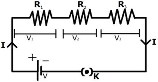
In the circuit given below if we need to find the potential drops through each resistor in series

V1 = Potential drop of R1 = I* R1
Similarly, V2= I*R2 and V3= I*R3
And power dissipated in each resistor,
P1= power dissipated in resistor R1= V1*I = V1^2/R1= I^2*R1
Similarly, we can find the power dissipated by R2 and R3.
Parallel combination of resistors
Below is the figure of the parallel combination of resistors.
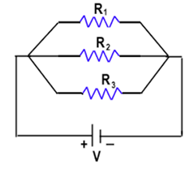
Two or more resistors are said to be in parallel if one end of all the resistors are joined together and similarly the other ends join together.
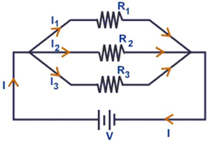
In parallel combination of the resistors
- Voltage is the same across all the resistors connected in parallel and is equal to the potential difference of the battery.
V1= V2= V3=V
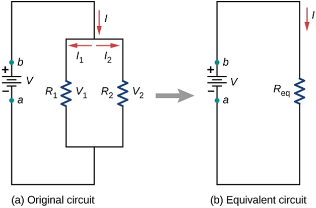
- In a parallel combination of resistors, the current is divided between the resistors such that the sum of currents through all the resistors are equal to the total current in the circuit.
I= I1+I2+ I3
Let Req= equivalent resistance of the circuit.
I= total current in the circuit
V= potential difference of the terminals of the battery
I1. I2 and I3 are the currents through R1, R2, and R3 respectively.
By using ohm's law we have
I1= V/ R1 , I2= V/R2 , I3= V/R3 and I= V/Req
If we put above values in I= I1 + I2 + I3
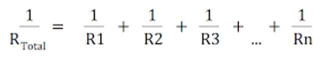
We will get 1/Req = 1/R1 + 1/R2 + 1/R3, This is the formula for finding equivalent resistance for the parallel combination of the resistors.
If we have two resistors in parallel shown below
Then equivalent resistance of the circuit will be given by
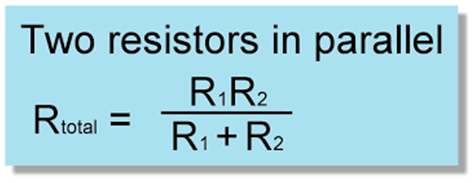
If we have ‘n’ resistors connected in parallel the equivalent resistance will be
Cells, EMF, and Internal resistance
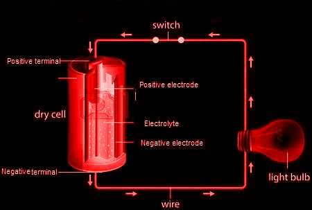
In the circuit given below a positive charge flows spontaneously in a conductor from higher potential to lower potential in the direction of the electric field. To maintain the current through the conductor, some external devices must do some work at a steady rate to take the positive charge from lower potential to higher potential. Such a device is the source of EMF ( electromotive force). These devices can be a battery, cell, or electrolytic solution.
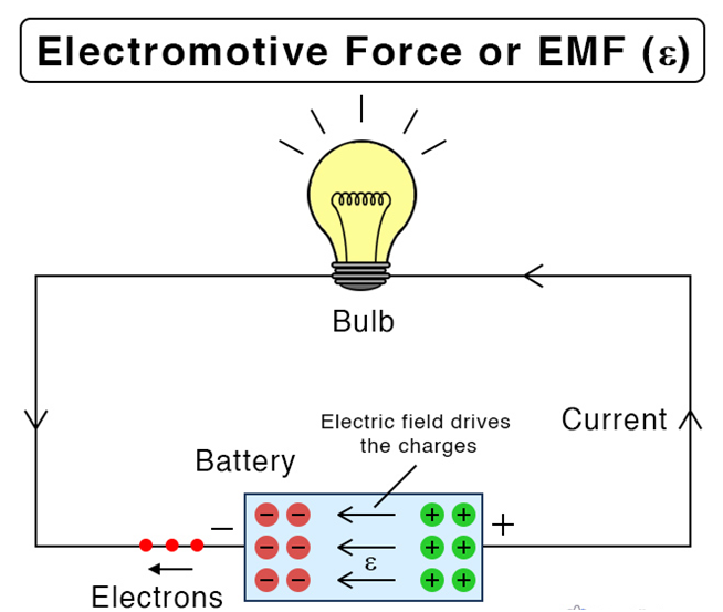
Electromotive force may be defined as the work done by the source in taking a unit positive charge from lower potential to higher potential. The EMF of a source is equal to the maximum potential difference between its terminals when it is in an open circuit. In other words, the emf of a source may be defined as the energy supplied by the source in taking a unit positive charge once round the complete circuit.
The term EMF- electromotive force is actually a misnomer. The emf is not a force at all. It is a special case of potential difference in which the circuit is open.
V= W/q, therefore emf has also the nature of work done per unit charge.
S.I. unit of EMF is Volt.
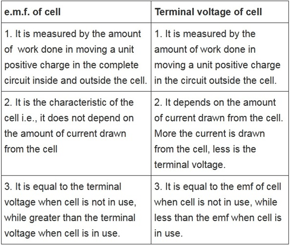
Before going ahead with the topic, Let's have a pause and first try to understand the difference between the EMF of a cell and the potential difference of the cell.
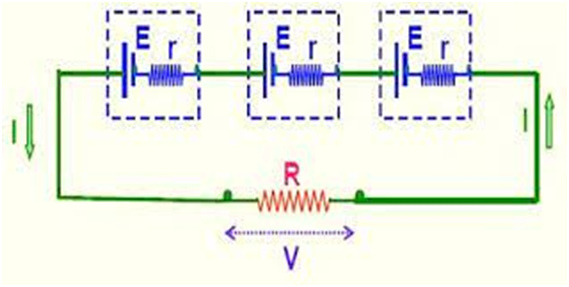
Relation between EMF, Internal resistance and terminal potential difference of the cell
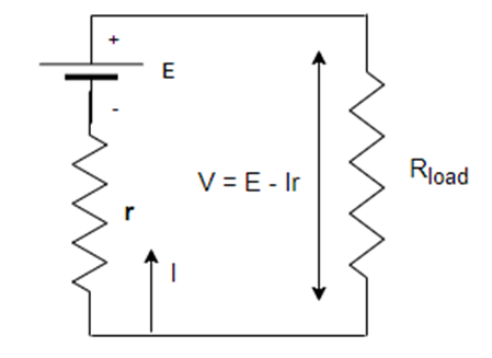
In the circuit, above we have a cell with EMF ‘E’ and internal resistance ‘r’ and it is connected with a load resistance ‘R’in series.
V= potential difference across the load resistance
Total resistance in the circuit= R+ r
Current I= E/(R+r)
So V (terminal potential difference ) = I*R = ER/(R+r)
Also by simplifying we get V= E- Ir
E= V+ I*r = I*R+ I*r = I( R+r)
Special Case:
- When the cell is open I=0 we have V open= E
Thus the potential difference across the terminals of the cell is equal to its emf when no current is being drawn from the cell.
- A real cell has always some internal resistance ‘r’, so when the current is being drawn from the cell, we have
V closed < E
Thus the potential difference across the terminal of a cell in a closed circuit is always less than its EMF
Combination of cells in series and parallel
Like capacitors and resistors, we can also group cells together in series and parallel combinations
Series combination of cells
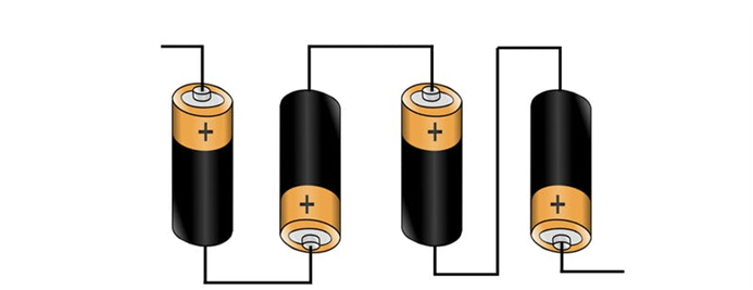
The above combination is the series combination of the cell, where the positive terminal of one cell is connected with the negative terminal of the other cell.
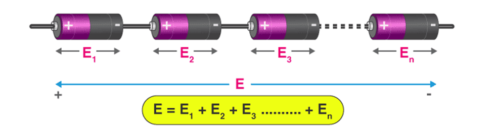
Then the total emf of the cell will be given by some of the emf of all the individual cells.
Suppose we have practical cells with internal resistance as shown in the figure below.
Then equivalent EMF ‘Eeq’ = E1 + E2 +E3
And total internal resistance req= r1+ r2+ r3
Here all the cells are identical having the same EMF and internal resistance
Eeq= 3E and req= 3r
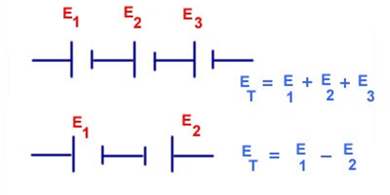
Therefore, for a combination of ‘n’ identical cells in series
Eeq= nE, equivalent emf will be ‘n’ times the emf of single-cell
req= nr, and equivalent internal resistance would be ‘n’ times the internal resistance of a single cell.
Also, take care of one more concept. If any one of the cells is connected in reverse, then we will subtract the emf of that cell.
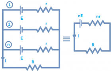
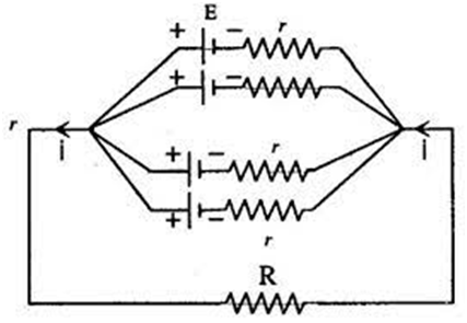
Combination of cells in parallel.
Below is the parallel connection of cells
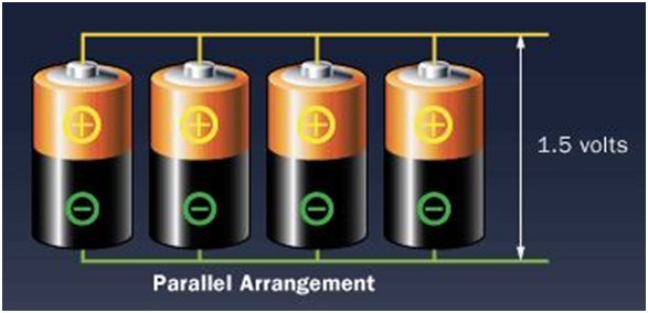
Here all the positive terminals of cells are joined together and similarly, the negative terminals are joined together.
Suppose we have two cells with emf

For parallel combinations of ‘n’ cells, equivalent emf and internal resistance is given by following relations.
A fun thing to do:
Below is the link to a simulation with which you can design your own circuits using various electrical elements like wire, batter, light bulb, resistor of different values, switch, fuse etc. Just as many circuits as you want and learn with fun.
What can you get from this?
- It can show the direction of conventional and electronic current
- Using voltmeter and ammeter in your circuit you can get the value of voltage and current.
- There is some advanced tools also that can change the wire resistivity and also the battery internal resistance
- Books Name
- Physics Book Part l and ll
- Publication
- Grow Career Publication
- Course
- CBSE Class 12
- Subject
- Physics
COMBINATION OF RESISTORS
SERIES AND PARALLEL
The connection is in such a manner that the current flowing through the 1st register has to then flow further through the 2nd register and then through 3rd. Therefore, a common current is flowing in connection with a resistor in series. At all point in the circuit, the current amoung the resistors is same. For example,
I1 = I2 = I3 = It = 2ma
All the resistors in series that is R1, R2, R3 have current I1, I2, I3 respectively and the current of the circuit is It.
Resistor in Parallel
Unlike, series connection, in parallel connection, current can have multiple paths to flow through the circuit, hence parallel connection is also current dividers. Common voltage drop is across the parallelly connected circuits/networks. At the terminals of the circuit, the voltage drop is always the same. For example
VR1=VR2=VR3=VRT=14V
![]()
The voltage across R1 is equal to the voltage across R2 and similarly, equal to R3 and hence the total voltage drop is equal to the voltage across the circuit. Reciprocal of individual resistance of each resistor and the sum of all the reciprocated resistance of resistor will us the total resistance of the circuit.
CELLS, EMF, INTERNAL RESISTANCE
What is an Electromotive Force (EMF) of a Cell?
The electrolyte has the same potential (emf) throughout the cell. The condition of no current flowing through a cell is also known as an open circuit. An open circuit result in a potential (emf) of the cell is equal to the difference of potentials (emf) of the electrodes. Anode has a positive potential (V+) whereas Cathode has a negative potential (-V–). This potential difference is known as the Electromotive Force (EMF).An electric battery is a device made up of two or more cells that make use of the chemical energy stored in the chemicals and converts it into electrical energy.