 Grow Career Publication
 Madhava Publications
1.Electromagnetic Induction
- Books Name
- Physics Book Part l and ll
- Publication
- Grow Career Publication
- Course
- CBSE Class 12
- Subject
- Physics
Chapter 6: Electromagnetic Induction
Magnetic flux
Magnetic flux is a measurement of the total magnetic field which passes through a given area. It is a useful tool for helping describe the effects of the magnetic force on something occupying a given area.
If we choose a simple flat surface with area A as our test area and there is an angle θ between the normal to the surface and a magnetic field vector (magnitude B) then the magnetic flux is
Φ=BAcosθ
1.Electromagnetic Induction
- Books Name
- Physics by Anshu Physics Book
- Publication
- Madhava Publications
- Course
- CBSE Class 12
- Subject
- Physics
Introduction
We have studied electrostatics and magnetostatics in previous chapters as two different phenomena. But later on, it was discovered that they are not two different phenomena. These are like two faces of the same coin. They are not independent but linked to each other under a wider category of interaction which is called electromagnetic interactions. Electromagnetic interactions are one of the four fundamental interactions of the universe.
In this unit, we will see that changing magnetic fields also produce emf and hence electric current.This phenomenon is called electromagnetic induction. We will discuss such phenomena in detail in this chapter.
Experiment of Faraday and Henry
Discovery of electromagnetic induction is based on a series of experiments carried out by Faraday and Henry. The theoretical explanation of the experiment was later given by Faraday and Lenz which are known as the laws of electromagnetic induction.
Note for the student: In the following experiments along with the observation, I have given the explanation of the observation too in blue color and used the word magnetic flux many times in that explanation which I have not discussed before. Students can read about the magnetic flux in the latter topic.
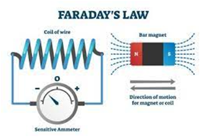
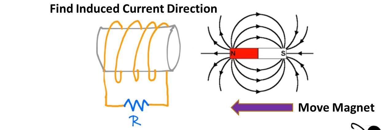
Experiment 1: A coil and a magnet
Consider a loop of wire, connected with a galvanometer and a bar magnet as shown in the figure. We will keep the wire loop fixed in place and the bar magnet can be moved back and forth as shown in the figure.
- Initially, when the magnet is far from the coil, there is no deflection in the coil, This is because no magnetic flux will be linked with the coil and hence the deflection of the galvanometer is zero.
- As the coil is moved near the coil, magnetic field lines will be linked with the coil and these field lines will change as the coil continues to move and the galvanometer will show deflection.
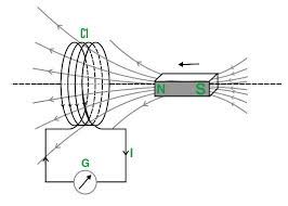
- Suppose as in figure ‘b’, a magnet is placed inside the coil and it is kept stationary, there will be no deflection in the galvanometer.
This happens because the magnetic flux linked with the coil is constant and does not change with time
Again like in figure ‘c’, if we now try to move the magnet away from the coil, we will again see that the galvanometer shows deflection but now in the opposite direction. Here magnetic flux
- linked with the coil is also changing, it is decreasing as the magnet is moving away from it.
- Now like in the figure ‘d’, if we keep the magnet at rest outside the coil, the galvanometer will show no deflection
This happens as the magnetic flux linked with the coil is constant when there is no relative motion between the coil and the magnet
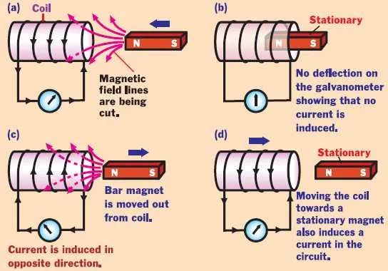
- If we now keep the magnet stationary and move the coil near the magnet, we will again observe that the galvanometer will show deflection like before.
- Deflection was found larger when we move the magnet faster near the coil keeping the coil fixed or moving the coil near the fixed magnet.
Conclusion: The results from the above experiment show that It is the relative motion between the magnet and the coil which is responsible for the generation ( induction ) of electric current in the coil.
Experiment 2: One coil with a galvanometer and another coil connected with a battery.
We have two coils C1 and C2. Coil C1 is connected with a galvanometer and coil C2 is connected with a battery source that produces a constant current.
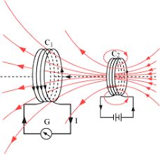
- Keep C1 fixed and move C2 toward C1, the galvanometer will show deflection. Now if we move coil C2 away from coil C1, again the deflection will produce in the galvanometer. Hence there will be an induced current in coil C1.
- Keep C2 fixed and move C1 toward C2, the galvanometer will show deflection. Now if we move coil C1 away from coil C2, again the deflection will produce in the coil. Hence there will be an induced current in coil C1.
Conclusion: Again it is the relative motion between the coils that induce the electric current
Experiment 3: Both coils are kept stationary
In this experiment, we have two coils C1 and C2. Coil C1 is connected with the galvanometer and C2 is connected with a battery and key k.
- When the key of the circuit is closed, there is a momentary deflection in the galvanometer
Explanation is that when the key is open, there would be no current in C2 and hence the magnetic field would also be zero. So there will be no magnetic flux linked with the coil, but when the switch is closed, there will be a sudden increase in current in Coil C2 and magnetic flux linked with C1 suddenly changes so there is momentarily deflection in the coil.
- There is no deflection in the galvanometer after the key of C2 is closed.
Explanation is that when there is a steady current in C2 and hence magnetic field produced by the C2 is also constant. So the magnetic flux linked with coil C1 will also remain the same and hence no current will be produced in C1 and hence the galvanometer shows zero deflection.
- When the key is opened again, there will be again momentarily deflection in the coil.
Explanation is that when the key is opened, the current in Coil C2 changes from a steady value to zero and hence produces a changing magnetic field. The magnetic flux linked with the coil also changes from a finite value to zero. And hence there is a momentarily induced current in the coil C1 and hence the galvanometer shows momentarily deflection.
Magnetic flux
There was a need for a mathematical tool to explain the series of experiments carried out by Faraday on electromagnetic induction.
So he defined the notion of magnetic flux ‘
The magnetic flux through any surface placed in a magnetic field is the total number of magnetic lines of force crossing this surface normally.
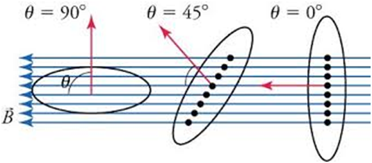
Magnetic flux would be maximum when
Magnetic flux will be zero when
Dimension of
In S.I. The unit of magnetic flux is Weber.
One weber is the flux when a uniform magnetic field of one tesla acts normally over an area of
S.I. unit is Weber and in C.G.S. The unit is maxwell.
How can magnetic flux links be changed?
Mathematically magnetic flux is equal to
So there are following ways to change the magnetic flux
- By changing the magnetic field
- By changing the area of the loop or closed circuit
- By changing the orientation of the closed circuit with respect to Magnetic flux.
We can either do one of the above-mentioned ways to change the magnetic flux or we can do more than one change simultaneously.
The Faraday Law of Induction
In the experiment discussed above, we have following observation that
- When there is a relative motion between the coil and the source of the magnetic field, an electric current is induced in the coil.
- The common point in all observations is that more deflection is produced when the magnet is moved rapidly near the coil.
Now we will use the concept of magnetic flux to explain how this happens.
Faraday explained that whenever there is relative motion between the coil and the magnet or a source of magnetic field ( current-carrying coil), the magnetic flux linked with the coil changes and thus an emf is induced in the coil and hence there is an induced electric current in the coil. He also noticed that in every experiment, emf induced is directly proportional to the rate of change of magnetic flux in the coil.
Faraday’s Law of Electromagnetic induction:
- Whenever the magnetic flux linked with a closed circuit changes, an emf (and hence a current) is induced in it which lasts only so long as the change in flux is taking place. This phenomenon is called electromagnetic induction.
- The magnitude of the induced emf is equal to the rate of change of magnetic flux linked with the closed circuit.
Mathematically,
For the N turn of the coil
Thus induced current emf can be increased by increasing the number of turns N of a closed coil.
2. Lenz's law and energy
- Books Name
- Physics Book Part l and ll
- Publication
- Grow Career Publication
- Course
- CBSE Class 12
- Subject
- Physics
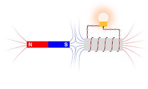
Lenz’s Law
Lenz’s law is given by a physicist of Germany named Heinrich Friedrich Lenz. He described the direction of electric current relative to the magnetic flux. He deduced that the direction of an induced current in a circuit is such as to oppose the change that causes it.
![]()
Applications of Lenz’s Law
- Braking systems in trains,
- Metal detectors,
- Eddy current dynamometers,
- AC Generators,
- Card Readers,
- Microphones, etc.
MOTIONAL ELECTROMOTIVE FORCE
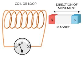
The process of induction occurs when a change in magnetic flux causes an emf to oppose that change. One of the main reasons for the induction process in motion. We can say, for example, that a magnet moving toward a coil generates an emf, and that a coil moving toward a magnet creates a comparable emf.
Let x be the distance between the resistance and the rod at any timer t . According to faraday’s law, emf produced in a loop due to change in magnetic flux is,
ε = – dφ/dT
φt (flux at any time t) = B . A
= B l x
⇒ d (φt )/dt = d (Blx)/dt
= Bl dx/dt
= Blv
Therefore,
ε = – dφ/dT
= Blv
Using Ohm’s law: V = IR or I = V/R
Current through the resistance R is,
I = Blv/R (in a clockwise direction)
Amount of charge (q) passed through the loop in time ‘t’ = Δφ/R
where Δφ = Total change in flux in time ‘t’.
ENERGY CONSIDERATION: A QUANTITATIVE STUDY
Let us consider a rectangular loop as shown in the figure above, with the sides PQ, QR, RS and SP. Here, the three sides of the loop are fixed and one of the sides, the side PQ, is free to move. Let r be the resistance of the movable arm under consideration.
loop be taken as ε, then the current in the loop can be given as,

![]()
The energy that goes into the motion of the rod in this system is dissipated in the form of heat given by,
Here we see that the value of PJ is equal to the value of P. the magnitude of the induced emf is,

However, as we know that,
And thus, from the above two equations, we can write,

EDDY CURRENTS
Eddy currents are currents which circulate in conductors like swirling eddies in a stream. They are induced by changing magnetic fields and flow in closed loops, perpendicular to the plane of the magnetic field. So far we have studied the electric currents induced in well defined paths in conductors like circular loops. Even when bulk pieces of conductors are subjected to changing magnetic flux, induced currents are produced in them. However, their flow patterns resemble swirling eddies in water. This effect was discovered by physicist Foucault (1819-1868) and these currents are called eddy currents
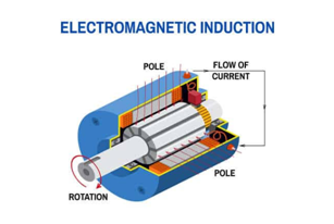
AC GENERATOR
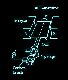
The phenomenon of electromagnetic induction has been technologically exploited in many ways. An exceptionally important application is the generation of alternating currents (ac). The modern ac generator with a typical output capacity of 100 MW is a highly evolved machine. In this section, we shall describe the basic principles behind this machine. The Yugoslav inventor Nicola Tesla is credited with the development of the machine.
Working of an AC Generator
When the armature rotates between the poles of the magnet upon an axis perpendicular to the magnetic field, the flux linkage of the armature changes continuously. As a result, an electric current flows through the galvanometer and the slip rings and brushes. The galvanometer swings between positive and negative values. This indicates that there is an alternating current flowing through the galvanometer.
Field
The field consists of coils of conductors that receive a voltage from the source and produce magnetic flux. The magnetic flux in the field cuts the armature to produce a voltage.
Armature
The part of an AC generator in which the voltage is produced is known as an armature. This component primarily consists of coils of wire that are large enough to carry the full-load current of the generator.
Prime Mover
The component used to drive the AC generator is known as a prime mover. The prime mover could either be a diesel engine, a steam turbine, or a motor.
Rotor
The rotating component of the generator is known as a rotor. The generator’s prime mover drives the rotor.
Stator
The stator is the stationary part of an AC generator. The stator core comprises a lamination of steel alloys or magnetic iron to minimize the eddy current losses.
Slip Rings
Slip rings are electrical connections used to transfer power to and fro from the rotor of an AC generator. They are typically designed to conduct the flow of current from a stationary device to a rotating one.
2. Lenz's law and energy
- Books Name
- Physics by Anshu Physics Book
- Publication
- Madhava Publications
- Course
- CBSE Class 12
- Subject
- Physics
Lenz’s Law
Faraday’s law gives the magnitude of the induced emf and Lenz's law gives the direction of the induced current.
In Faraday’s Experiment it was seen that when a magnet is moved toward the coil, the galvanometer shows deflection in one direction and when the magnet is moved away from the coil, the galvanometer will show deflection in another direction.
In 1834, German physicist Heinrich Friedrich Lenz deduced a rule, known as Lenz’s law which gives the polarity of the induced emf. The statement of the law is the polarity of induced emf is such that it tends to produce a current in such a way that it opposes the change in magnetic flux that produced it.
Let us understand this with the following figure.
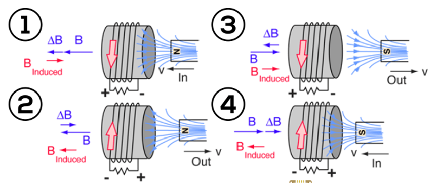
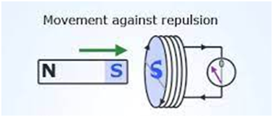
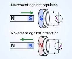
- In figure 1, the North pole of the magnet is moved toward the coil, So the magnetic flux linked with the coil will be increasing, so the current in the coil will induce in such a way that the induced magnetic field will oppose the increase in magnetic flux in the coil ( Induced B is in opposite to B/ change In B), as shown in (1) part of the figure above. The induced current will be in a counter-clockwise direction.
- In figure 2, the North pole of the magnet is moving out from the coil, So the magnetic flux linked with the coil will be decreasing. So the induced current will be such that the induced magnetic field will be in the direction of B. Induced current will be in the clockwise direction.
- In figure 3, The South pole of the magnet is moving out of the coil, so the magnetic flux is decreasing and so induced magnetic is in the same direction as B. Induced current will be in a counterclockwise direction.
- In figure 4, The south pole of the magnet is moving in toward the coil, So the magnetic flux is increasing and so the induced magnetic field is in the opposite direction as B. Induced current will be in a clockwise direction.
The above four examples are sufficient to understand Lenz's law but I will still try to give another example.
In the first figure, The south pole of the magnet is approaching the coil, so the induced current in the coil will try to oppose the motion of the magnet. So the induced current is clockwise as seen from the magnet so that The front face of the coil will make the south pole of the induced magnetic field and hence will try to oppose the motion of the south pole of the moving magnet towards it.
In the following figure, the south pole of the magnet is moving away from the coil, so the induced current will be such that its induced magnetic field will make the north pole on the front face of the coil. Thus the induced current will be counterclockwise.
Refer to the figure given below if you are having difficulty identifying the poles of the electromagnet ( magnetism induced in the coil due to induced electric current in the coil.
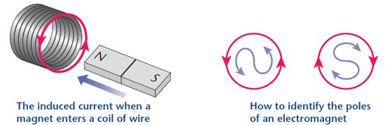
- If induced current is counter clockwise then there will be a North pole of the electromagnet.
- If induced current is in clockwise direction then there will be a south pole of the electromagnet and vice versa.
Conservation of Energy.
You might be wondering how it is possible that a current is suddenly induced in the coil with no battery connected to it. Have you thought about it earlier? Where does this electrical energy in the coil come from?
Is energy conserved in this process?
The answer is Definitely Yes, Energy is definitely conserved in the process. As energy conservation is a fundamental law it cannot be violated.
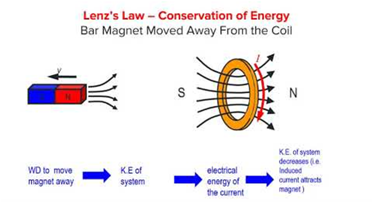
Suppose the north pole of the magnet is moving out from the coil, so the current induced in the coil will be such that it will try to attract the magnet and hence the motion of the magnet which is trying to move out from the coil is opposed.
So an external force has to do some work on the magnet to keep it moving with uniform speed away from the coil.
This work done by the external force is actually converted into the electrical energy of the system.
So Lenz's law is consistent with the conservation of energy.
Motional Electromotive Force
Let us consider a straight conductor PQ moving in a uniform magnetic field.
Consider the conductor PQ moving with speed ‘v’ as shown on a rectangular U-shaped metal rod MSRN.
As rod PQ moves as shown the area enclosed by the closed-circuit rectangle SPQR will decrease as the rod PQ moves.
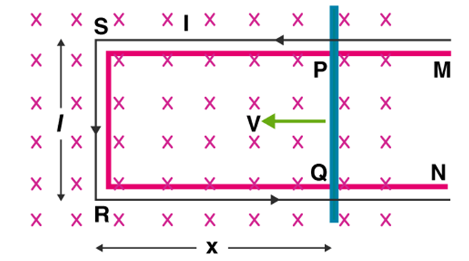
Due to the change in the Area of the rectangle SPQR, magnetic flux linked with the rectangle changes and hence an emf is induced at the ends of rod PQ and hence there will be an induced current in the rectangle SPQR as shown in the figure.
Here A= length * width= l*x
As the rod PQ moves, the width of the rectangle ‘x’ varies with time.
As by Faraday’s law, emf induced is equal to the rate of change of magnetic flux. we have,
We can also understand this induction of emf at the ends of the rod PQ using the concept of magnetic force.
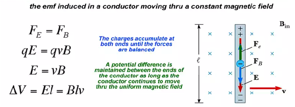
Moving a rod in a magnetic field is equivalent to changes moving in a uniform field, as the metal rod PQ contains charges.
And charges moving in magnetic field B experience a force
By using the concept of magnetic force according to the figure given above, we can say that the direction of the force on the negative and positive charges inside the rod will be opposite directions and hence charges start accumulating at the end and hence causing an emf at the end of the conductor PQ.
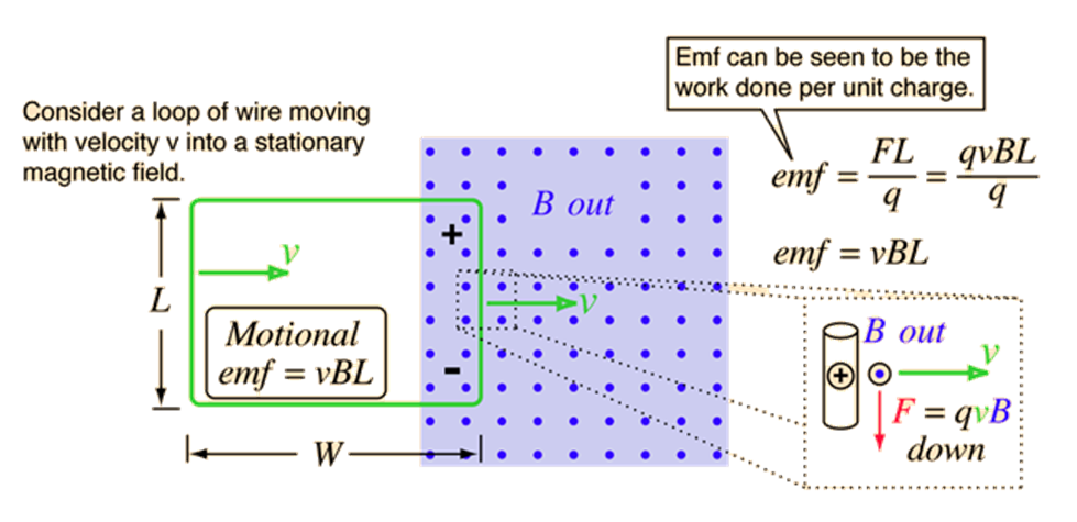
Also when a closed wire enters a region of a magnetic field then also a current will be induced in the closed rectangle wire. Refer to the figure given below
Energy Consideration: Quantitative Study
We have discussed Lenz's Law and how it is consistent with the conservation of energy and also discussed motional emf ( emf induced in a conductor due to its motion in a uniform magnetic field.
Now we will move further in the discussion of motional emf.
Suppose the resistance of the closed circuit is ‘R’.
The induced current in the circuit will be given by,
Also, when a current-carrying conductor of length ‘L’ carries current ‘I’ moves in magnetic field B.
Magnetic force experienced by the conductor is given by
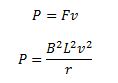
We can say that the arm PQ is pushed at a constant speed.
So the power required to do so is
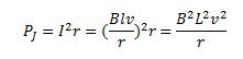
The power dissipated as heat
Thus the mechanical energy( work done by an external force) which was needed to move the arm PQ gets converted into electrical energy (induced emf) and then to thermal energy (energy lost as heat). There is an interesting relationship between the charge flow through the circuit and the change in magnetic flux
From Faraday's law induced emf is
However by Ohm’s law
Comparing (1) and (2) we get,
Where
Eddy current
By changing magnetic fields, current can be induced in not only conducting coils but also conducting sheets or blocks.
Whenever the magnetic flux linked with a metal, sheet, or block changes, an emf is induced in it.
The induced current flows in closed paths in planes perpendicular to the lines of forces throughout the body of the metal.
Eddy currents are the currents induced in solid metallic masses when the magnetic flux threading through them changes.
Eddy currents also oppose the change in magnetic flux, so their direction is given by Lenz’s Law.
An undesirable effect of the eddy currents.
Eddy currents are produced inside the iron cores of the rotating armatures of electric motors and dynamos, and also in the cores of transformers, which experience flux changes when they are in use. Eddy currents cause unnecessary heating and wastage of power. The heat produced by eddy currents may even damage the insulation of the coils.
Applications of eddy currents.
There are many applications in the following devices.
- Induction furnace: If a metal species is placed in a rapidly changing magnetic field ( produced by electromagnet produced by high-frequency a.c.), very large eddy currents are set up. The heat produced is sufficient to even melt the metal. This process is used in the extraction of some metals from ores.
- Electric brakes: A strong magnetic field is applied to the rotating drum attached to the wheel. Eddy currents set up in the drum exerts a torque on the drum so as to stop the train.
- Energy meters: In energy meters used for measuring electrical energy, the eddy currents induced in an aluminum disc are made used.
- Electromagnetic shielding: Eddy currents may be used for electromagnetic shielding.
Inductance
An electric current can be induced in a coil by flux change produced by another coil in its vicinity ( mutual inductance) or flux change produced by the same coil (self-inductance).
In both cases, the flux through a coil is proportional to the current.
Further, the geometry of the coil does not vary with time then.
For a closely wound coil of N turns, the same magnetic flux is linked with all the turns.
Flux linked with 1 turn of the coil is
Flux linked with N turn of the coil will be
So for N turn
To remove the proportionality sign, we will put one constant ‘L’
L is proportionality constant and is called Inductance.
Inductance is a scalar quantity and depends only on the geometry of the coil and intrinsic material property.
Unit of Inductance is Henry (H)
Dimension:
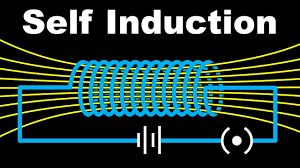
Self-inductance
Self Inductance is the phenomenon of production of induced emf in a coil when a changing current passes through it.
Suppose we have a coil, connected with a battery and a tapping switch connected in series. Initially, the switch is open and there is no current in the coil and hence the magnetic flux linked with the coil is also zero.
As soon as we tap the key to close, Current flows in the circuit and produces a magnetic field and hence some magnetic flux linked with the coil increases from zero to maximum value and the induced current flows in the opposite direction of battery current in accordance with Lenz’s law.
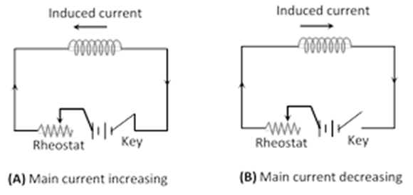
When the tapping switch is again opened, the current and hence the magnetic flux through the coil decreases from maximum to zero and the induced current flows in the same direction as that of the battery current.
Coefficient of self-induction: At any instant the magnetic flux linked with a coil is proportional to the current I through it.
Here L= inductance or the coefficient of self-inductance.
The self-inductance of a coil is numerically equal to the magnetic flux linked with the coil when a unit current flows through it.
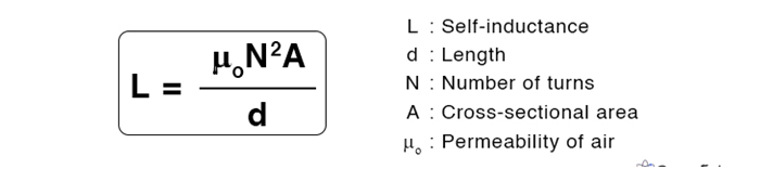
Self-induction of a long solenoid
The self-inductance of the solenoid depends on the geometry and the magnetic permeability of the core material.
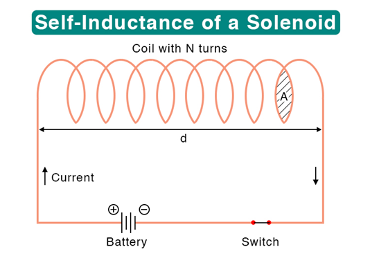
Self-inductance depends on
- No of turns: Larger the number of turns in the solenoid, the larger is its Self Inductance.
- Area of cross-section: Larger the area of cross-section of the solenoid, the larger its self-inductance.
- Permeability of core material: The self-inductance of a solenoid increases μr times if it is wound over an iron core of relative permeability.
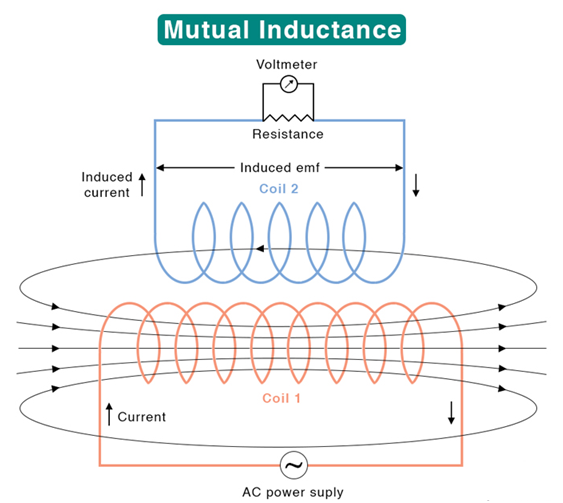
Mutual Inductance
Mutual Inductance is the phenomenon of the production of induced emf in one coil due to a change in the current in the neighboring coil.
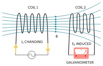
In the example shown in the figure, we have coil 1 ( primary coil) with a variable ac source. The magnetic field caused by coil 1 linked with and an emf is induced in coil 2 ( secondary coil ) which can be seen in the voltmeter connected with coil1.
Coefficient of mutual Inductance: At any instant magnetic flux linked with the secondary coil is proportional to the current in the primary coil.
Here M is proportionality constant and called the coefficient of Mutual Induction or Mutual Inductance.
The mutual inductance of the two coils may be defined as the induced emf set up in one coil when the current in the neighboring coil changes at the unit rate.
Mutual Inductance of two long solenoid:
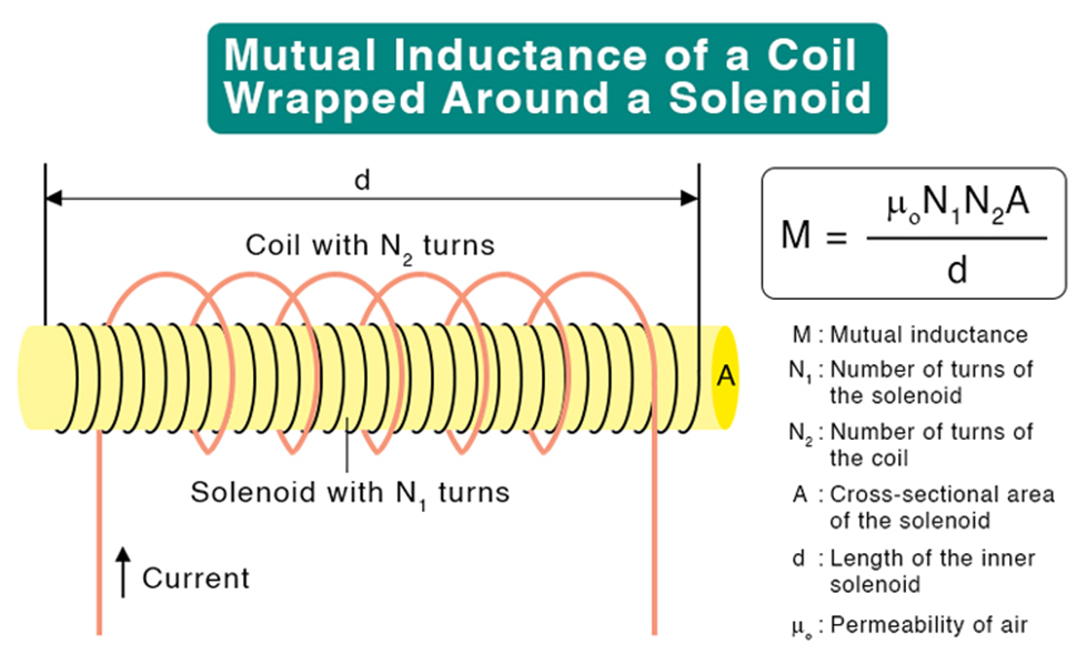
Here A= common cross-section area of the two solenoid
The mutual inductance of two coils is the property of their combination. It does not matter which one of them functions as the primary or the secondary coil. This fact is known as the reciprocity theorem.
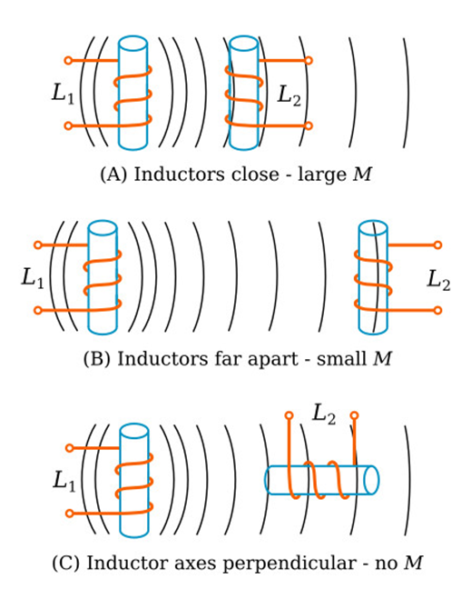
Factors on which mutual inductance depends.
The mutual inductance of two solenoids depends on their geometry and the magnetic permeability of the core material.
- Number of turns: Larger the number of turns in the two solenoids will be their mutual inductance.
- Common Cross-section Area: Larger the common cross-section area of the two solenoids, the larger will be their mutual inductance.
- Relative separation: Larger the distance between the two solenoids, the smaller will be the magnetic flux linked with the secondary coil and hence the smaller the mutual inductance. ( refer to figures A and B below)
- Relative orientation of the coil: M is maximum when the entire flux of primary is linked with the secondary. M is minimum when the coils are perpendicular to each other as shown in figure C
AC Generator
A generator or dynamo is a device that converts mechanical energy into electrical energy.
An a.c. generator is the one that produces a current that alternates or changes its direction regularly after a fixed interval of time
Principle: Electromagnetic induction is the working principle of the a.c. generator. When a closed coil is rotated in the presence of a uniform magnetic field, flux linked with the coil continuously changes and an induced emf and hence a current is set up in it.
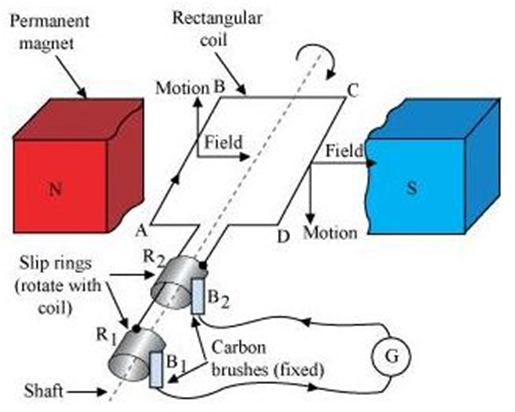
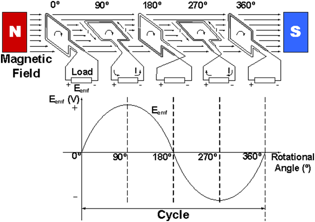
The Function of AC Generator
To create a strong magnetic field, the coil is rotated in the magnetic field. An EMF is induced in one direction as a coil goes up through the magnetic field on one side. An EMF is induced in the reverse direction as the coil rotates and this side of the coil moves down and another side of the coil moves up. The direction of the induced EMF is determined using Fleming’s right-hand rule. Every cycle, this process is repeated, and the EMF generated is of the alternating type.
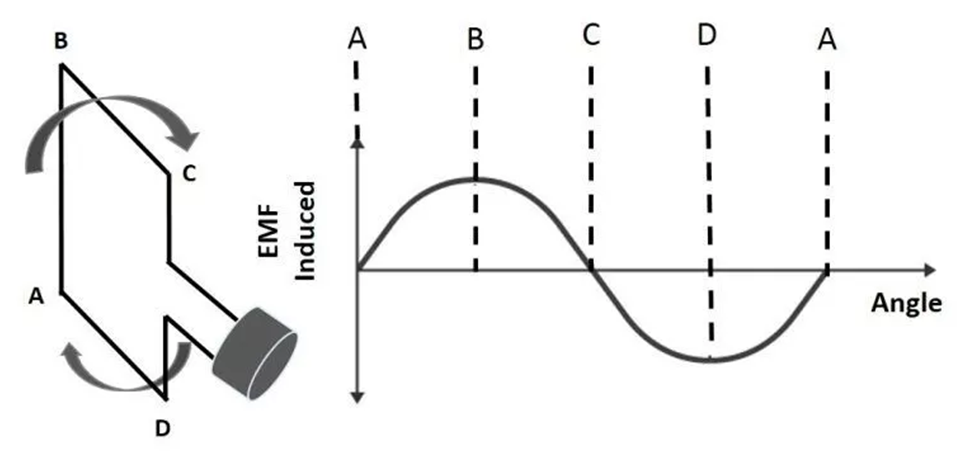
Diagram Showing Different Positions of a Coil
A graph depicting the output of an AC generator is displayed above. The description of the letters are as follows:
A – When the coil is at 0 degrees, it moves parallel to the magnetic field’s direction and so produces no EMF.
B – The coil moves at 90 degrees to the magnetic field and hence induces the most EMF when it is at 90 degrees.
C – When the coil is rotated 180 degrees, it moves parallel to the magnetic field again, causing no EMF to be generated.
D – When the coil is at 270 degrees, it goes back to 90 degrees to the magnetic field, inducing the maximum EMF. The induced EMF in this case is the polar opposite of B’s.
A – The coil has completed one rotation when it reaches 360 degrees when it moves parallel to the magnetic field and produces zero EMF.
Consider a rectangular coil with ‘N’ turns rotating in a homogeneous magnetic field ‘B’ with an angular velocity of ‘’. At every time ‘t’, the angle between the magnetic field ‘B’ and the normal to the coil is given by, θ = ωt.
The magnetic flux is perpendicular to the plane of a coil in this location, and it is given by B Cos ωt. The magnetic flux associated with a coil of N turns is equal to ɸ = B Cos ωt A, where A is the coil’s area. Faraday’s Laws of Electromagnetic Induction determine the induced EMF in the coil.
Maximum value of emf will be when wt=90
Induced current
The flux linkage of the armature varies continually as it revolves between the poles of the magnet on an axis perpendicular to the magnetic field. An electric current travels through the galvanometer, slip rings and brushes as a result. The galvanometer changes its value from positive to negative. This implies that the galvanometer is receiving an alternating current. Fleming’s Right-Hand Rule can be used to determine the direction of the induced current.