 Madhava Publications
 Grow Career Publication
- Books Name
- Physics Book Part l and ll
- Publication
- Grow Career Publication
- Course
- CBSE Class 12
- Subject
- Physics
Capacitors and capacitance
CAPACITORS AND CAPACITANCE
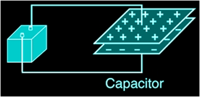
A capacitor is a two-terminal electrical device that possesses the ability to store energy in the form of an electric charge. It consists of two electrical conductors that are separated by a distance. The space between the conductors may be filled by vacuum or with an insulating material known as a dielectric. The ability of the capacitor to store charges is known as capacitance. C =Q/v
THE PARALLEL PLATE CAPACITOR
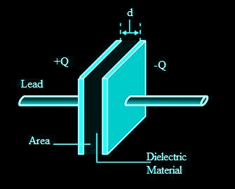
A parallel plate capacitor consists of two large plane parallel conducting plates separated by a small distance We first take the intervening medium between the plates to be vacuum. The effect of a dielectric medium between the plates is discussed in the next section.
![]()
COMBINATION OF CAPACITORS
Capacitance in Series
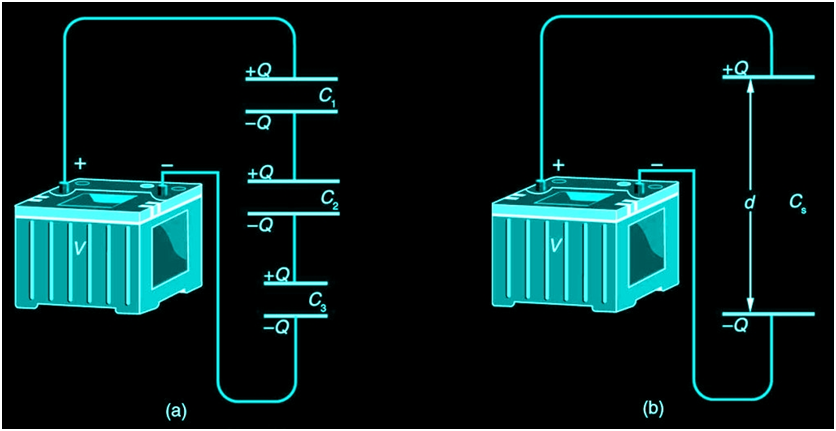
Figure 1a shows a series connection of three capacitors with a voltage applied. As for any capacitor, the capacitance of the combination is related to charge and voltage by C= Q/V
Note in Figure 1 that opposite charges of magnitude Q flow to either side of the originally uncharged combination of capacitors when the voltage V is applied. Conservation of charge requires that equal-magnitude charges be created on the plates of the individual capacitors, since charge is only being separated in these originally neutral devices. The end result is that the combination resembles a single capacitor with an effective plate separation greater than that of the individual capacitors alone. Larger plate separation means smaller capacitance. It is a general feature of series connections of capacitors that the total capacitance is less than any of the individual capacitances.
dividual capacitors Solving C=Q/V for V gives V=Q/C. The voltages across the individual capacitors are thus
V1=Q/C1,V2=Q/C2, and V3=Q/C3.
The total voltage is the sum of the individual voltages:
V = V1 + V2 +V3.
Now, calling the total capacitance CS for series capacitance, consider that
V=Q/Cs =V1+V2+V3.
Entering the expressions for V1, V2, and V3, we get
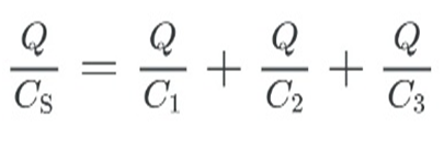
where “…” indicates that the expression is valid for any number of capacitors connected in series. An expression of this form always results in a total capacitance CS that is less than any of the individual capacitances C1, C2, …, as Example 1 illustrates.
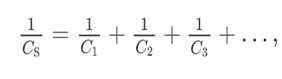
Total Capacitance in Series, Cs
Total capacitance in series:
1/CS = 1/C1 + 1/C2 … ..
Capacitors in parallel
Two capacitors arranged in parallel. In this case, the same potential difference is applied across both the capacitors. But the plate charges (±Q1) on capacitor 1 and the plate charges (±Q2) on the capacitor 2 are not necessarily the same:
Q1 = C1V, Q2 = C2V
The equivalent capacitor is one with charge
Q = Q1 + Q2
and potential difference V.
Q = CV = C1V + C2V
The effective capacitance C is, C = C1 + C2
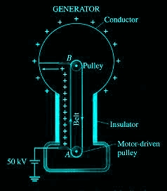
VAN DE GRAAFF GENERATOR
A Van de Graaff generator is an electrostatic generator, invented by Robert J. Van de Graaff. It uses a moving belt that accumulates charge on a hollow metal structure designed like a globe, placed on the top of a column that is insulating in nature and thus, creating a very high electric potential in the order of a few million volts. This results in a very large electric field that is used to accelerate charged particles.
Working principle of Van de Graaff Generator
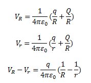
Let us consider a large spherical shell of radius R. If we place a charge of magnitude Q on such a sphere, the charge will spread uniformly over the surface of the sphere and the electric field inside the sphere will be equal to zero, and that outside the sphere will be due to the charge Q placed at the centre of the sphere.
At the surface of the small sphere:
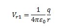
At the large spherical shell of radius R:
If we consider the total charges in the system, that is, q and Q, then the total potential energy due to the system of charges can be given as,