 Madhava Publications
 Grow Career Publication
1. Electric current
- Books Name
- Physics Book Part l and ll
- Publication
- Grow Career Publication
- Course
- CBSE Class 12
- Subject
- Physics
Chapter 3: Current Electricity
Current Electricity
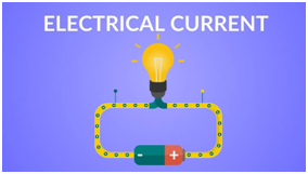
Electric current is the flow of electrons through a complete circuit of conductors. It is used to power everything from our lights to our trains.In these activities, students will explore different kinds of circuits and investigate what is required to make a complete circuit.
Types of Current
There are two types of current
1. Direct Current (DC)
2. Alternating Current (AC)
Direct Current
The current electricity whose direction remains the same is known as direct current. Direct current is defined by the constant flow of electrons from a region of high electron density to a region of low electron density.
Alternating Current
The current electricity that is bidirectional and keeps changing the direction of the charge flow is known as alternating current. The electrical outlets at our home and industries are supplied with alternating current.
2. Ohm's Law
- Books Name
- Physics Book Part l and ll
- Publication
- Grow Career Publication
- Course
- CBSE Class 12
- Subject
- Physics
OHM’S LAW
A basic law regarding flow of currents was discovered by G.S. Ohm in.1828,Ohm’s law states that the current through a conductor between two points is directly proportional to the voltage across the two points.
V = IR
LIMITATIONS OF OHM’S LAW
Although Ohm’s law has been found valid over a large class of materials, there do exist materials and devices used in electric circuits where the proportionality of V and I does not hold.
- Ohm’s law is also not applicable to non – linear elements. Non-linear elements are those which do not have current exactly proportional to the applied voltage that means the resistance value of those elements changes for different values of voltage and current. Examples of non – linear elements are the thyristor.
- The relation between V and I depends on the sign of V. In other words, if I is the current for a certain V, then reversing the direction of V keeping its magnitude fixed, does not produce a current of the same magnitude as I in the opposite direction. This happens for example in the case of a diode.
RESISTIVITY OF VARIOUS MATERIALS
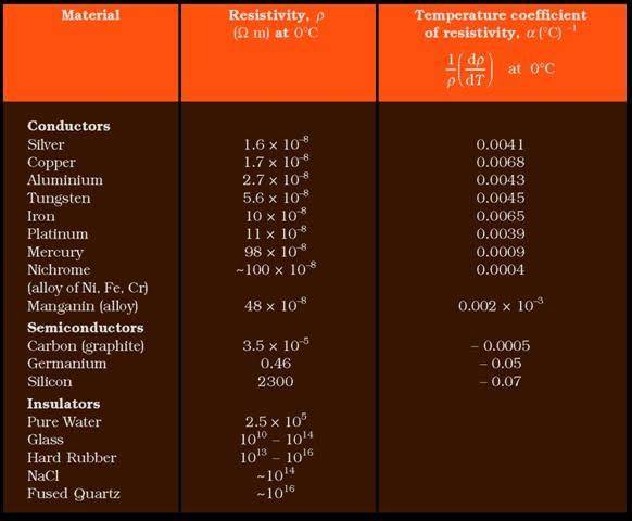
TEMPERATURE DEPENDENCE
The resistivity of a material is found to be dependent on The temperature. Different materials do not exhibit the Same dependence on temperatures. Over a limited range Of temperatures, that is not too large, the resistivity of a Metallic conductor is approximately given by,
ρT = ρ0 [1 + α (T–T0)]
ELECTRICAL ENERGY, POWER
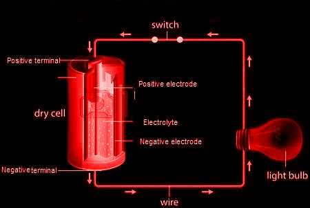
A cell has two terminals – a negative and a positive terminal. The negative terminal has the excess of electrons whereas the positive terminal has a deficiency of electrons. Let us take the positive terminal as A and the electrical potential at A is given by V(A). Similarly, the negative terminal is B and the electrical potential at B is given by V(B). Electric current flows from A to B, and thus V(A) > V (B).The potential difference between A and B is given by
V = V(A) – V(B) > 0
3. Combination of resistors
- Books Name
- Physics Book Part l and ll
- Publication
- Grow Career Publication
- Course
- CBSE Class 12
- Subject
- Physics
COMBINATION OF RESISTORS
SERIES AND PARALLEL
The connection is in such a manner that the current flowing through the 1st register has to then flow further through the 2nd register and then through 3rd. Therefore, a common current is flowing in connection with a resistor in series. At all point in the circuit, the current amoung the resistors is same. For example,
I1 = I2 = I3 = It = 2ma
All the resistors in series that is R1, R2, R3 have current I1, I2, I3 respectively and the current of the circuit is It.
Resistor in Parallel
Unlike, series connection, in parallel connection, current can have multiple paths to flow through the circuit, hence parallel connection is also current dividers. Common voltage drop is across the parallelly connected circuits/networks. At the terminals of the circuit, the voltage drop is always the same. For example
VR1=VR2=VR3=VRT=14V
![]()
The voltage across R1 is equal to the voltage across R2 and similarly, equal to R3 and hence the total voltage drop is equal to the voltage across the circuit. Reciprocal of individual resistance of each resistor and the sum of all the reciprocated resistance of resistor will us the total resistance of the circuit.
CELLS, EMF, INTERNAL RESISTANCE
What is an Electromotive Force (EMF) of a Cell?
The electrolyte has the same potential (emf) throughout the cell. The condition of no current flowing through a cell is also known as an open circuit. An open circuit result in a potential (emf) of the cell is equal to the difference of potentials (emf) of the electrodes. Anode has a positive potential (V+) whereas Cathode has a negative potential (-V–). This potential difference is known as the Electromotive Force (EMF).An electric battery is a device made up of two or more cells that make use of the chemical energy stored in the chemicals and converts it into electrical energy.
4. Law's and Bridge
- Books Name
- Physics Book Part l and ll
- Publication
- Grow Career Publication
- Course
- CBSE Class 12
- Subject
- Physics
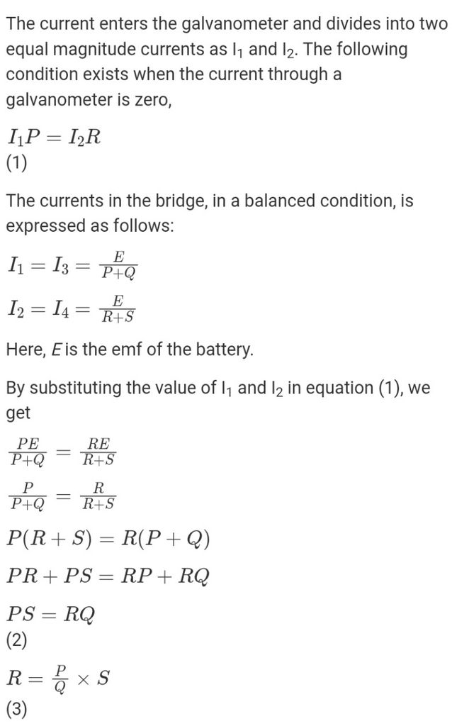
KIRCHHOFF’S RULES
Electric circuits generally consist of a number of resistors and cells interconnected sometimes in a complicated way. The formulae we have derived earlier for series and parallel combinations of resistors are not
Mvalways sufficient to determine all the currents and potential differences in the circuit. Two rules, called Kirchhoff’s rules, are very useful for analysis of electric circuits.
V = ε + I r
WHEATSTONE BRIDGE
The Wheatstone bridge works on the principle of null deflection, i.e. the ratio of their resistances are equal and no current flows through the circuit. Under normal conditions, the bridge is in the unbalanced condition where current flows through the galvanometer.
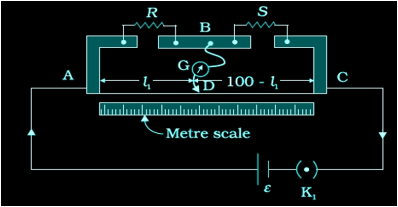
METER BRIDGE
A meter bridge consists of a wire of length 1 m and of uniform cross-sectional area stretched taut and clamped between two thick metallic strips bent at right angles with two gaps across which resistors are to be connected. The end points where the wire is clamped are connected to a cell through a key. One end of a galvanometer is connected to the metallic strip midway between the two gaps. The other end of the galvanometer is connected to a jockey which moves along the wire to make electrical connection.

POTENTIOMETER
This is a versatile instrument. It is basically a long piece of uniform wire, Sometimes a few meters in length across which a standard cell is Connected. In actual design, the wire is sometimes cut in several pieces Placed side by side and connected at the ends by thick metal strip.