 Madhava Publications
 Grow Career Publication
- Books Name
- Physics by Anshu Physics Book
- Publication
- Madhava Publications
- Course
- CBSE Class 12
- Subject
- Physics
Conductor and Capacitors
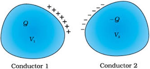
A capacitor is a two-conductor system separated by an insulator. The conductors have charges say Q1 and Q2 and potential V1 and V2. In practice, we have two conductors having charge Q and -Q and the potential difference between them are V= V1-V2.
Note: Even a single conductor can be considered as a capacitor assuming the other at infinity.
Conductors may be charged by connecting them to the terminals of a battery. Q is the charge of one conductor, though the total charge of the capacitor is zero.
- The electric field in the region between the conductors is proportional to the charge Q
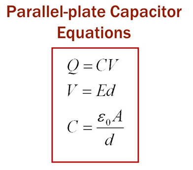
Now we also know that V= E*d ………….(2)
where V= potential difference between the conductors.
E= electric field in the region in between the conductors of capacitor
d= distance between two conductors of the capacitors
So we get 1 and 2 equations that
Q
To remove the proportionality, you need to put some proportionality constant.
Q= C *V ………… (3)
where C= proportionality constant is called the capacitance of the capacitor, it basically tells us about the charge holding capacity of a particular capacitor for a given voltage difference across it.
- Capacitance is independent of Q and V
- C is only dependent on the size, shape and separation of the system of conductors
- S.I. unit of capacitance C is Farad. 1 F= 1 C/V
- For large C, V is small for given Q and Q is very large for given V. Hence large charges can be stored by providing a small potential difference.
- For small C, V is large for given Q and Q is small for given V. we would need a large potential difference to get more charges on the capacitor.
Types of capacitors and their capacitances
Capacitors come in different shapes, sizes and separations between the conductors and hence differ in their capacitances.
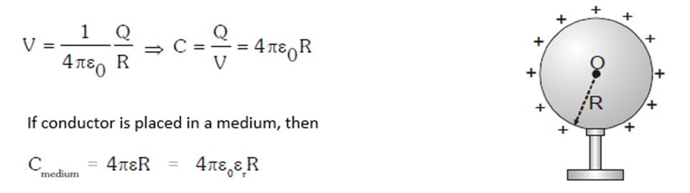
1. Spherical conductor: It is just a single spherical conductor that can store charge on its surface and is assumed to have another surface at infinity. If the potential of the spherical conductor is V and Q is the charge stored then capacitance can be found as below.
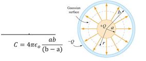
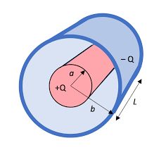
2. Spherical capacitor: It is basically two concentric hollow spheres of inner radius a and outer radii ‘b’. Then capacitance C is given by the following formula.
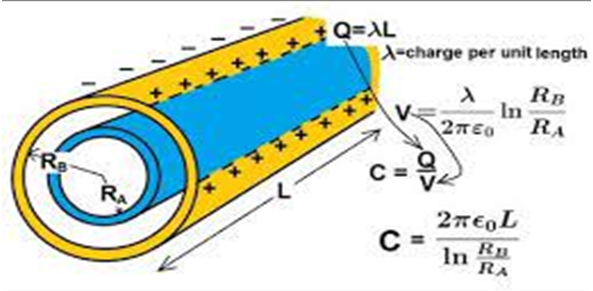
3. Cylindrical capacitor: It is made of two concentric cylindrical conductors, having length ‘l; and inner and outer radius as ‘a’ and ‘b’ respectively.
4. Parallel Plate capacitor
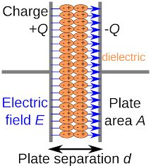
In a parallel plate capacitor, we have two parallel plates of surface area ‘A’ and the distance between plates is ‘d’. The capacitance of parallel is given by the following formula.
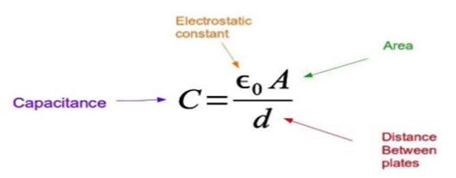
This is how we can find the capacitance of the parallel plate capacitor.
Below are some equations used in the case of parallel plate capacitors.
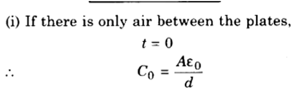
Effect of dielectric on capacitance
Suppose we don't have air or vacuum between the conductors of the capacitor but the space between them is filled by an insulator or a dielectric of dielectric constant ‘ K’ or relative permittivity ‘
Suppose we have a parallel plate capacitor filled with dielectric in all space between the plates. Then the new capacitance becomes K time the previous value of capacitance with air/vacuum between the plates.
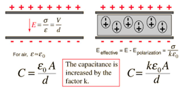
This is true not only for parallel plate capacitors but valid with every kind of capacitor spherical and cylindrical too. When we filled the space between the conductor their capacitance becomes K or
When we fill dielectric of thickness ‘t’ in between the plates of parallel plate capacitors such that t<d.
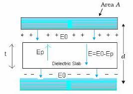
It means the space between the plates is filled with air in thickness (d-t) and filled with dielectric in thickness ‘t’.
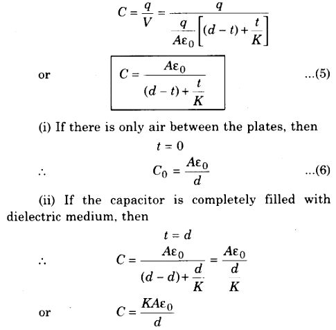
Above the formula, we use to find the capacitance if a dielectric of thickness t< d is introduced between the plates in a parallel plate capacitor.
Some definitions :
Dielectric constant
We know that when we insert dielectric inside the capacitor, capacitance becomes C= K* Co
So K= C/Co
The dielectric constant may be defined as the ratio of the capacitance of the capacitor when it is filled with a dielectric to the capacitance when air/ vacuum is in between.
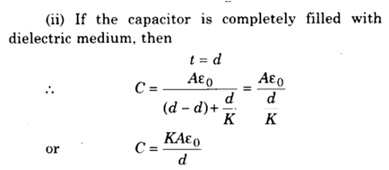
Combination of capacitors
We can combine several capacitors and capacitance C1, C2… Cn to obtain a system with some effective capacitance C. The effective capacitance depends on the way individual capacitors are combined.
The two simplest ways are
- Capacitors in series .
- Capacitors in parallel.
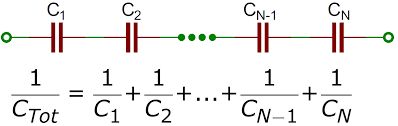
Capacitors in series
When the second plate of one capacitor is directly connected with the first plate of another capacitor, this is called a series combination of the capacitors.
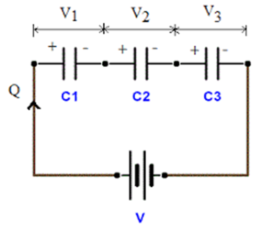
In series, the combination of the capacitor charge is the same for all the capacitors and the voltage of the battery is the sum of the voltage drop of the individual capacitor.
V= V1 + V2+ V3 ; Q1= Q2= Q3= Q
We can conclude that the effective capacitance of a capacitor in series is the ‘n’ number of capacitors connected in series.
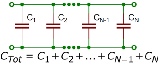
Capacitor in parallel
In the figure given below, capacitors are connected in parallel combinations. In parallel combination we have the following:
- The voltage difference is the same across every capacity
V1= V2= V3= V
- A charge is different across each capacitor and the total charge in the circuit is actually the sum of the charge on the individual capacitor
Q= Q1+ Q2+ Q3
Q= Q1 + Q2+ Q3
Ceq*V= C1*V+ C2*V+ C3*V
Ceq= C1 + C2 + C3

If we have ‘n’ capacitors in parallel then the effective capacitance of the parallel combination of capacitors is given by following
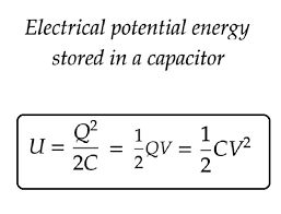
Energy stored in a capacitor
In the process of charging the capacitor, some energy is stored in the capacitor. If you are wondering where this energy comes from. Imagine the process of charging the capacitor.
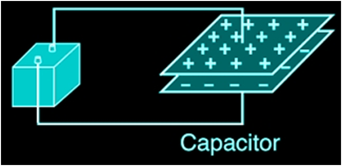
In the circuit given below, the positive terminal of the battery is connected with the upper plate and the negative terminal is connected with the lower plate. So the upper plate is at a higher potential than the lower.
Initially, we assume that both the plates are uncharged and then after connecting it with the battery, there starts a transfer of charge from the lower conductor to the upper conductor bit by bit, so at the end, the upper plate gets ‘Q’ charge while the lower plate gets ‘-Q’ charge when fully charged.
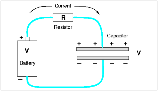
Since the charge is being transferred from lower potential to higher potential, work will be done externally and this external work is stored in the form of energy in the capacitor. The various formula for energy stored in the capacitor in terms of charge, capacitance and the potential difference between the plates is given below
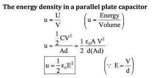
The energy density in a parallel plate capacitor = Energy/volume
A fun thing to do.
Below is the link to the simulation of the capacitor. In this simulation, we have a battery connected with a parallel plate capacitor.
What you have to do -
- The potential of the battery can be changed by moving the slider up and down given on the battery.
- You can increase the plate area by dragging the arrow diagonally as shown in the simulator screen
- And you can also increase or decrease the distance between the plates by dragging the arrow up and down
- Take out the potentiometer by dragging it and connect it with two plates of the capacitor and measure the potential difference on the plates
What you can get from here.
For a given combination of battery potential, separation of plates and plate area you can see the value of the following quantities by clicking on the checkbox before it.
- Capacitance
- Charge on plates
- Energy stored in the capacitor
Also, you can see the visually
- Charges on the plated
- Electric field
- Current direction
- And bar graphs
- Books Name
- Physics Book Part l and ll
- Publication
- Grow Career Publication
- Course
- CBSE Class 12
- Subject
- Physics
Capacitors and capacitance
CAPACITORS AND CAPACITANCE
A capacitor is a two-terminal electrical device that possesses the ability to store energy in the form of an electric charge. It consists of two electrical conductors that are separated by a distance. The space between the conductors may be filled by vacuum or with an insulating material known as a dielectric. The ability of the capacitor to store charges is known as capacitance. C =Q/v
THE PARALLEL PLATE CAPACITOR
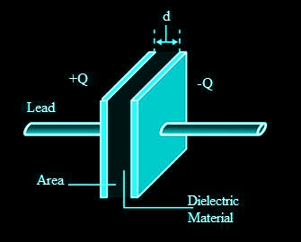
A parallel plate capacitor consists of two large plane parallel conducting plates separated by a small distance We first take the intervening medium between the plates to be vacuum. The effect of a dielectric medium between the plates is discussed in the next section.
![]()
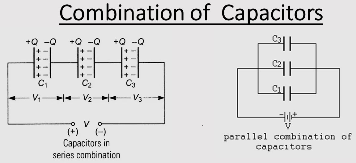
COMBINATION OF CAPACITORS
Capacitance in Series
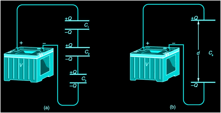
Figure 1a shows a series connection of three capacitors with a voltage applied. As for any capacitor, the capacitance of the combination is related to charge and voltage by C= Q/V
Note in Figure 1 that opposite charges of magnitude Q flow to either side of the originally uncharged combination of capacitors when the voltage V is applied. Conservation of charge requires that equal-magnitude charges be created on the plates of the individual capacitors, since charge is only being separated in these originally neutral devices. The end result is that the combination resembles a single capacitor with an effective plate separation greater than that of the individual capacitors alone. Larger plate separation means smaller capacitance. It is a general feature of series connections of capacitors that the total capacitance is less than any of the individual capacitances.
dividual capacitors Solving C=Q/V for V gives V=Q/C. The voltages across the individual capacitors are thus
V1=Q/C1,V2=Q/C2, and V3=Q/C3.
The total voltage is the sum of the individual voltages:
V = V1 + V2 +V3.
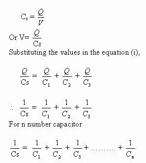
Now, calling the total capacitance CS for series capacitance, consider that
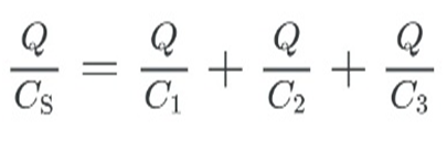
V=Q/Cs =V1+V2+V3.
Entering the expressions for V1, V2, and V3, we get
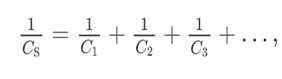
where “…” indicates that the expression is valid for any number of capacitors connected in series. An expression of this form always results in a total capacitance CS that is less than any of the individual capacitances C1, C2, …, as Example 1 illustrates.
Total Capacitance in Series, Cs
Total capacitance in series:
1/CS = 1/C1 + 1/C2 … ..
Capacitors in parallel
Two capacitors arranged in parallel. In this case, the same potential difference is applied across both the capacitors. But the plate charges (±Q1) on capacitor 1 and the plate charges (±Q2) on the capacitor 2 are not necessarily the same:
Q1 = C1V, Q2 = C2V
The equivalent capacitor is one with charge
Q = Q1 + Q2
and potential difference V.
Q = CV = C1V + C2V
The effective capacitance C is, C = C1 + C2
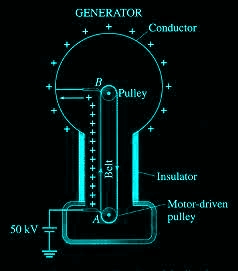
VAN DE GRAAFF GENERATOR
A Van de Graaff generator is an electrostatic generator, invented by Robert J. Van de Graaff. It uses a moving belt that accumulates charge on a hollow metal structure designed like a globe, placed on the top of a column that is insulating in nature and thus, creating a very high electric potential in the order of a few million volts. This results in a very large electric field that is used to accelerate charged particles.
Working principle of Van de Graaff Generator
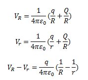
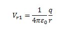
Let us consider a large spherical shell of radius R. If we place a charge of magnitude Q on such a sphere, the charge will spread uniformly over the surface of the sphere and the electric field inside the sphere will be equal to zero, and that outside the sphere will be due to the charge Q placed at the centre of the sphere.
At the surface of the small sphere:
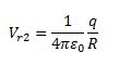
At the large spherical shell of radius R:
If we consider the total charges in the system, that is, q and Q, then the total potential energy due to the system of charges can be given as,