 Kaysons Publication
Errors
ERRORS
The result of every measurement by any measuring instrument contains some uncertainty this uncertainty is called errors. The errors in a measurement is equal to the difference between the true value and the measured value of any quantity.
Errors = True value – Measured value
Absolute Errors:- the several values obtained in an experiment measured are a1, a2, a3….an the arthmetic mean of these values will be
![]()
Now error in first measurement = Da1 = amean –a1
Similarly in second measurement = Da2 = amean –a2 and so on
![]() Relative error:Relative error=∆ameanamean
Relative error:Relative error=∆ameanamean![]()
![]()
Combination of errors (maximum possible error) Addition or subtraction
![]()
![]()
Product or multiplication
Let
![]()
![]()
Division
![]()
![]()
![]()
(4) Powers
Let C = anbm
![]()
CONCEPT WITH EXAMPLES
Role of constants
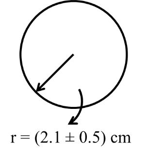
The radius of sphere is measured to be (2.1 ± 0.5) cm and is surface area with error limits.
Solution:
Surface area = A = 4pr2
![]()
![]()
![]()
Now% error
![]()
= 47.62 %
Other way
= 4 p r2
![]()
= 55.4 cm2
![]()
![]()
![]()
= 26.4 cm2
Now (A ± DA)
= (55.4±26.4)![]()
FINDING QUANTITY
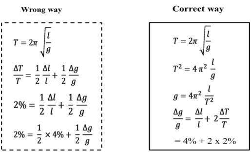
Percentage error in determining of acceleration of gravity with the help of simple Pendulum time period .![]() Given error in length of pendulum 4% while in The time period it is 2% then percentage error in g = ?
Given error in length of pendulum 4% while in The time period it is 2% then percentage error in g = ?
Solution
![]()
LEAST COUNT AND DIFFERENT UNITS
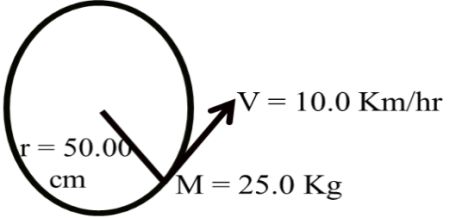
If a particle of mass m = 25.0 Kg is moving in a circular path of radius r = 50.00 cm with constant speed of v = 10.0 Km/hr them find error in force required by particle.
Now Given
m = 25.0 Kg
= L.c. = 0.1
V = 10.0 Km/h
= L.c = 0.1
DV = 0.1, V = 10
R = 50.00 cm
Dr = 0.001, r = 50cm
NOTE: never change units in error.
Least count
25.00 – L.c = 0.01
16.50 – 50 –L.c = 0.01
76.03 – 03 –L.c = 0.01
15.0002 –L.c = 0.0001
17.030 – L.c = 0.01
Solution:
![]()
![]()
![]()
![]()
![]()
![]()
= 1.21 x 2= 2.42% Ans.
UNIQUE CONCEPT
Calculate focal length of a spherical Mirror from the following observations Object distance u = (50.1 ± 0.5) cm. and image distance v = (20.1 ± 0.2) cm.
![]()
![]()
![]()
= 14.3 cm
Now
![]()
![]()
![]()
![]()
![]()
± 0.4 cm
Note: Similar case in resistance connected in parallel combinations
![]()
SIGNIFICANT FIGURES
The number of significant figures of a numerical quantity is the number of reliably known digits it contains:
Rules:
1. Zeros at the beginning of a number are not significant.
Ex. 0.0523 – there S.f. (5, 2, 3)
2. Zeros within a number are significant.
Ex: 2056 –Four S.f. (2, 0, 5, 6)
3. Zeros at the end of a number after decimal points are significant.
Ex. 3702.0 –five S.f. (3, 7, 0, 2, 0)
Errors,Vernier calipers and Screw Gauge
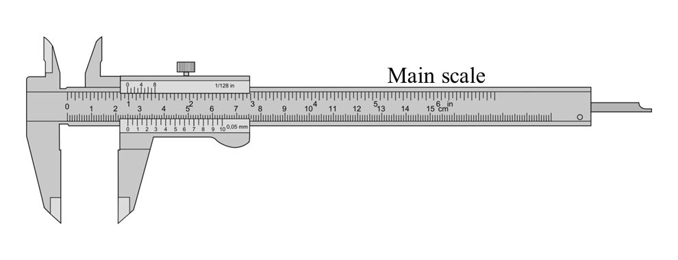
VERNIER CALIPERS
To measure length accurately upto 0.1 mm or 0.01 mm Vernier Calipers and Screw gauge are used
VERNIER CALIPERS
Parts of Vernier Calipers
(i) Main scale
(ii) Vernier Scale
(iii) Metallic Strip
PRINCIPLE OF VERNIER CALIPERS
N VSD = (n -1) MSD
![]()
1 MSD -1VSD = 1 MSD ![]()
![]()
LC or VC ® Smallest distance that can be accurately measured with
Vernier Scale
![]()
READING A VERNIER CALIPERS
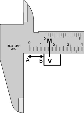
If we have to measure a length AB, the end A is coincided with the zero of main scale, suppose the end B lies between 1.0 cm and 1.1 cm on the main scale. Then,
![]()
Let 5th division of Vernier scale coincides with 1.5 cm of main scale.
Then, ![]()
Thus, we can make the following formula,
Total reading = N + n x VC
Here, N = main scale reading before on the zero of the Vernier scale.
n = number of Vernier division which just coincides with any of the
main scale division.
Zero Error and Zero Correction
If the zero of the Vernier scale does not coincide with the zero
of main scale when jaw B touches A and the straight edge of D
touches the straight edge of C, then the instrument has an error called zero error. Zero error is always algebraically subtracted from measured length.
Zero correction has a magnitude equal error but its given is opposite to that of the zero error. Zero correction is always algebraically added to measured length.
Zero error ® algebraically subtracted
Zero correction ® algebraically added
POSITIVE AND NEGATIVE ZERO ERROR
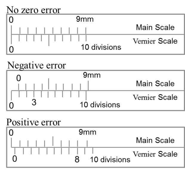
If zero of Vernier scale lies right of the main scale the zero is positive and if it lies to the left of the main scale the zero error is negative (when jaws A and B are in contact)
Positive zero error = (N + x x VC)
Here, N = main scale reading on the left of zero of Vernier scale.
X = Vernier scale division which coincides with any main scale division.
When the Vernier zero lies before the main scale zero the error is said to be negative zero error. If 8th Vernier scale division coincides with the main scale division, then
Negative zero error = -[0.00 cm + 8 x VC]
= -[0.00 cm +8 x 0.01 cm]
= -0.08 cm
SUMMARY
1. VC=LC=1MSDn=Smallest division on main scale number of division on vernier scale=1 MSD-1VSD![]()
2. In ordinary Vernier calipers, 1 MSD = 1mm and n = 10
![]()
3. Total reading = (N + n x VC)
4. Zero correction = -zero error
5. Zero error is algebraically subtracted white the zero correction is algebraically added.
6. If zero of Vernier scale lies to the right of zero of main scale the error is positive. The actual length in this case is less than observed length.
7. if zero of Vernier scale lies to the left of zero of main scale the error is negative and the actual length is more than the observed length.
8. Positive zero error = (N + x x VC)
Example
The smallest division on main scale of a Vernier calipers is 1 mm and 10 Vernier division coincide with 9 main scale divisions. While measuring the length of a line, the zero mark of the Vernier scale lies between 10.2 cm and 10.3 cm and the third division of Vernier scale coincides with a main scale division.
(a) Determine the least count of the calipers
(b) Find the length of the line
Solution: ![]()
![]()
![]()
SCREW GAUGE
Principle of a Micrometer Screw
The least count of Vernier calipers ordinarily available in the laboratory is 0.01 cm. when lengths are to be measured with greater accuracy, say upto 0.001cm, screw gauge and speedometer are used which are based on the principle of micrometer screw
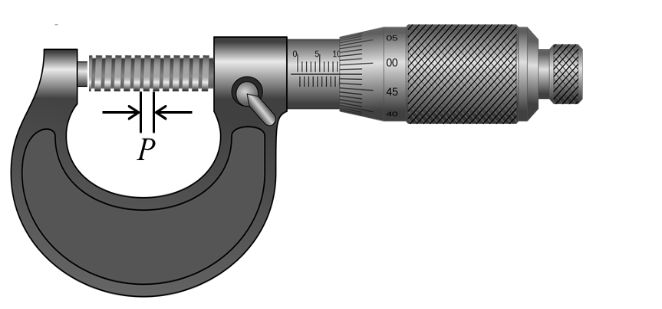
If an accurately cut single threaded screw is rotated in a closely fitted nut, then in addition to the circular motion of the screw there is a linear motion of the screw head in the forward or backward direction, along the axis of the screw. The linear distance moved by the screw, when it is given one complete rotation is called the pitch (p) of the screw. This is equal to the distance between two consecutive threads as measured along the axis of the screw. In most of the cases, it is given one complete rotation is called the pitch (p) of the screw. In most of the cases, it is either 1 mm or 0.5 mm. A circular cap is fixed on one end of the screw and the circumference of the cap is normally divided into 100 or 50 equal parts. If it is divided into 100 equal parts,
then the screw moves forward or backward by ![]() of the pitch, if the circular scale is rotated through one circular scale division. It is circular scale division. It is the minimum distance which can be accurately measured and so called the least Count (LC) of the screw.
of the pitch, if the circular scale is rotated through one circular scale division. It is circular scale division. It is the minimum distance which can be accurately measured and so called the least Count (LC) of the screw.
Thus, ![]()
If pitch is 1 mm and there are 100 divisions on circular scale then,
![]()
= 0.001cm = 10mm
Since, LC is of the order of 10mm, the screw is called micrometer screw.
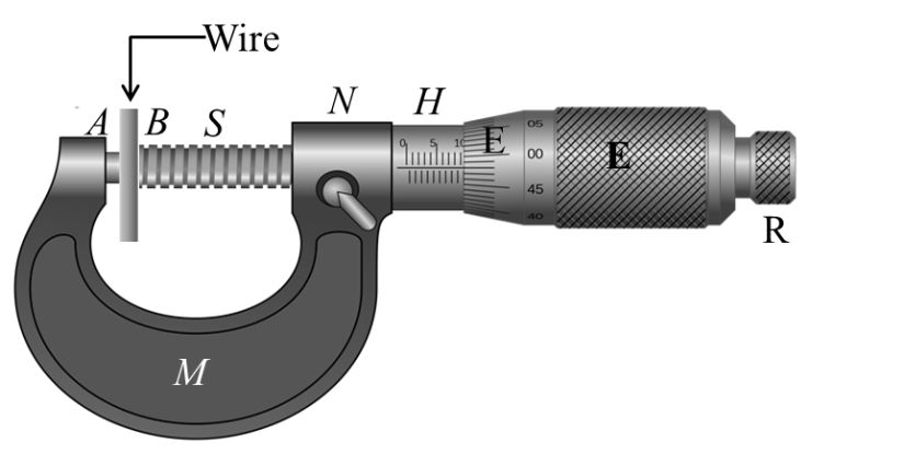
SCREW GAUGE
SCREW GAUGE
Screw gauge works on the principle of micrometer screw. It consists of a U –Shaped metal frame M. At one end of its is fixed a small metal piece A. it is called stud and it has a plane face. The other end N of M carries a cylindrical millimeter depending upon the pitch of the screw. This scale is called linear scale or pitch scale.
A nut is threaded through the hub and the frame N. through the nut moves a screw S. the fount face B of the screw, facing the plane face A is also plane, A hollow cylindrical cap K is capable of rotating over the hub when screw is rotated. As the cap is rotated the screw either moves in head scale. In an accurately adjusted instrument when the face A and B are just touching each other. Zero of circular scale should coincide with zero of linear scale.
To measure Diameter of a given wire using a screw gauge
If with the wire between plane faces A and B, the edge of the cap lies ahead of N th division of linear scale, and nth division of circular scale lies over reference line.
Then, Total reading = N + n x LC

ZERO ERROR AND ZERO CORRECTION
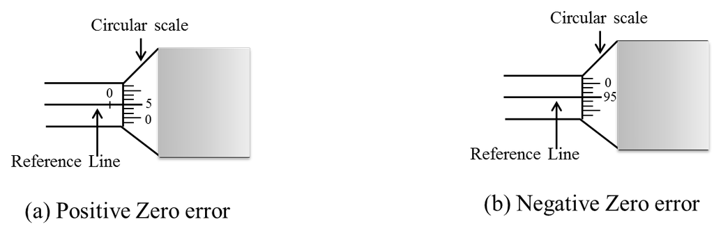
ZERO ERROR AND ZERO CORRECTION
If zero mark of circular scale does not coincide with the zero of the pitch scale when the faces A and B are just touching each other, the instrument is acid to possess zero error. If the zero of the circular scale advance beyond the reference line the zero is positive and zero correction is positive. If it is left behind the reference line the zero is positive and zero negative. For example, if zero of circular scale advance beyond the reference line by 5 divisions, zero correction = + 5 x (LC) and if the zero of circular scale is left behind the reference line by 6 divisions, zero corrections = -5 x (LC)
Example The pitch of a screw gauge is 1 mm and there are 100 divisions on circular scale. When faces A and B are just touching each without putting anything between the studs 32nd divisions of the circular scale (below its zero) coincides with the reference line. When a glass plate is placed between the studs, the linear scale 4 division and the circular scale reads 16 divisions. Find the thickness of the glass plate. Zero of linear scale is not hidden from circular scale when A and B touches each other.
Solution: ![]()
= 0.01 mm
As zero is not hidden from circular scale when A and B touches each other. Hence, the screw gauge has positive error.
![]()
Linear scale reading = 4 x (1mm) =4 mm
Circular scale reading = 16 x (0.01 mm) = 0.16mm
Measured reading = (4 + 0.16)mm = 4.16mm
Absolute reading = Measured reading = -e = (4.16 – 0.32) mm = 3.84 mm
Therefore, thickness of the glass plate is 3.84 mm.