 Param Publication
 PathSet Publications
Introduction
- Books Name
- CBSE Class 6 Science Book
- Publication
- Param Publication
- Course
- CBSE Class 6
- Subject
- Science
ELECTRICITY
It is the branch of physics which deals with the study of interaction of one charge to the another charge. It can be divided into two part :
(i) Static Electricity (ii) Current Electricity
(a) Static Electricity : The branch of physics which deals with the study of the electric charges at rest and their effects is known as electrostatic or static electricity.
(b) Current Electricity : The branch of physics which deals with the study of the electric charges in motion and their effects is known as current electricity.
Use of Electricity: We use electricity for many purposes to make our tasks easier. For example, we use electricity to operate pumps that lift water from wells or from ground level to the roof top tank. Electricity makes it possible to light our homes, roads, offices, markets and factories even after sunset. This helps us to continue working at night.
Source of Electricity: Mainly two types of Sources of Electricity
1. Power Station: It is a Main Source of Electricity. It produces and supply huge amount of Electricity. All the high voltage equipment get the supply from power station.
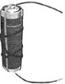
2. Electric Cells (Batteries) :It gives little amount of Electricity. It is portable and safe.
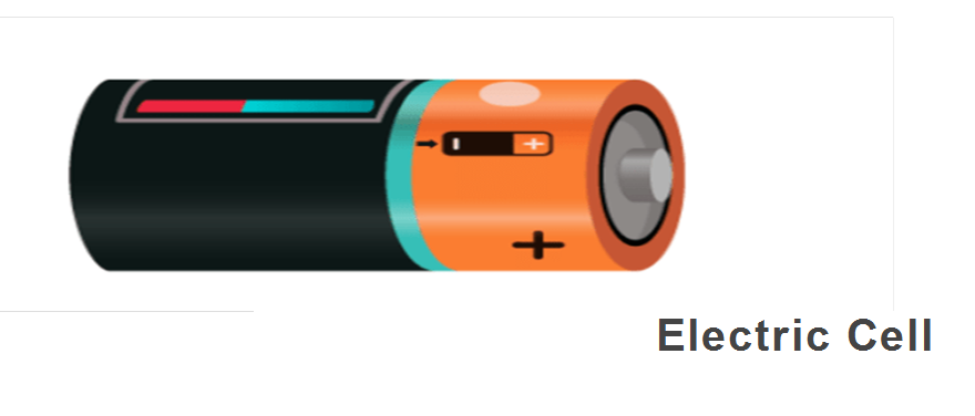
Electric cell
- Books Name
- CBSE Class 6 Science Book
- Publication
- Param Publication
- Course
- CBSE Class 6
- Subject
- Science
ELECTRIC CHARGE
From the study of atomic structure we know that an atom consists of a central part called nucleus and around the nucleus (called extra-nucleus) there are a number of electrons revolving in different paths or orbits. The nucleus consist of protons and neutrons. A proton is a positively charged particle while a neutron has no charge. Therefore, the nucleus of an atom bears a positive charge. An electron is a negatively charged particle having magnitude of negative charge equal to the magnitude of positive charge on a proton. Normally, the number of electrons is equal to the number of protons in an atom. Therefore, an atom is neutral as a whole, the negative charge on electrons cancelling the positive charge on protons. This leads to the conclusion that under ordinary conditions, a body is neutral, i.e. it exhibits no charge. When a body has deficiency or excess of electrons from the normal, it is said to be charged or electrified.
Types of Charge :
There are two types of charges known as positive and negative charges. All objects normally contain equal amount of positive and negative charges and are therefore, electrically neutral. When we comb dry hair, the comb gets charged and can pick small pieces of paper brought near it. When we rub a glass rod with silk cloth or a piece of ebonite rod with woolen material, the charge acquired by a glass rod rubbed with silk is called a positive charge. and that on ebonite rod, is called a negative charge. Glass rod and ebonite rod will attract each other while two glass rods as well as two ebonite rods will repel each other.
Unit of charge S. I. unit : Coulomb (C)
Properties of charge
(i) Charge is conserved during any process.
Example : Chemical reaction, nuclear reaction,etc.
(ii) Charge is quantized: Electric charge always occurs as some integral multiple of fundamental unit of charge (e).
Example : The amount of charge present on a body depends on the number of electrons given out or taken by the body, then Q = ± ne. Where n = 1, 2 ,3.......∞ n ≠ 2 /3 , 1 /2 or any fraction
(iii) Charge is always associated with mass.
(iv) Charge is transferable: If a charged body is put in contact with an uncharged conducting body, then it becomes charged due to transfer of electrons from one body to another, this process is called conduction.
(v) Charge resides on the outer surface of a conductor.
(vi) Similar charges repel each other while opposite charges attract.
(vii) Repulsion is sure test for electrification of bodies.
(viii) Electroscope is a device used to confirm the presence of charge and its nature on a body.
Electric cell
- Books Name
- Class 6 Science Book
- Publication
- PathSet Publications
- Course
- CBSE Class 6
- Subject
- Science
Introduction
Advantages of Electricity
- Light in our houses, offices, roads etc. even past sunset
- To operate pumps which in turn have a lot of applications
- Electrical appliances like refrigerator, fans etc.
- Building houses, installing equipment etc.
Current
- Current is the flow of particles in a particular direction. E.g air currents that cause winds or water currents.
- When particles flow in an electric circuit to produce electricity, it is called an electric current.
Electric current
- The flow of electric charges in a circuit is called an electric current. The direction is taken from the positive terminal to the negative terminal of the battery in an external circuit
Electric cell
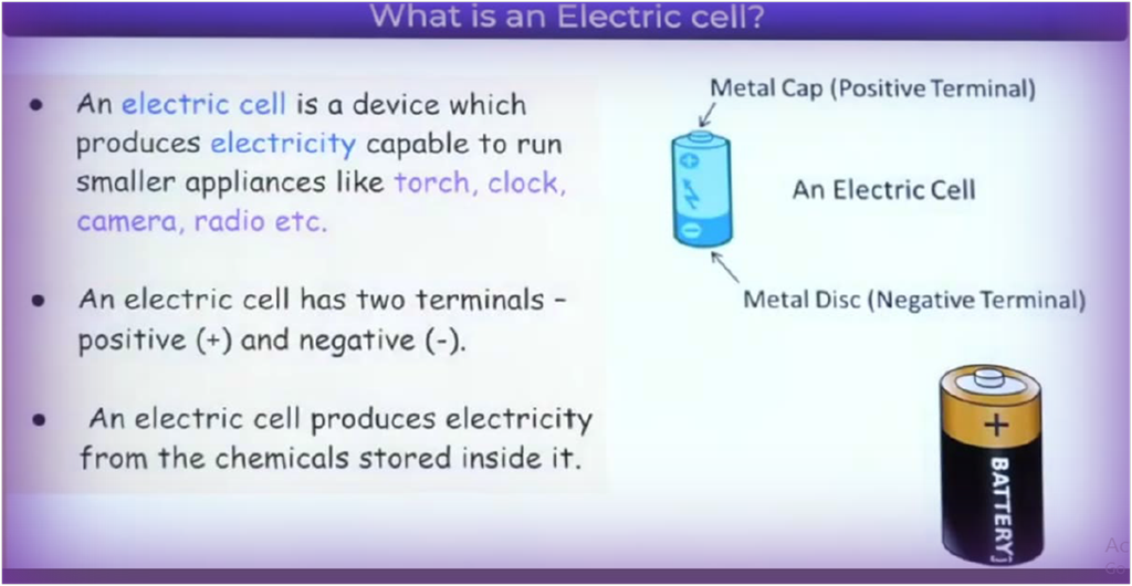
Features of an Electric Cell:
- It is a small cylindrical structure which helps in operating the devices.
- A small metal cap is placed on one side and a metal disc is present on the other side.
- All cells have two terminals: Positive and Negative.
- The metal cap and metal disc are positive (+) and negative (-) terminals of the electric cell respectively.
- Chemical energy is converted into electrical energy inside a cell. When the chemicals are exhausted, the cell stops working.
We use electric cells to supply the energy needed for electrons to move around an electric circuit. A battery is a group of two or more electric cells that are connected. The electric cell system works to generate electricity.
Power station: Electricity that we use at homes, in our factories, is supplied from a power station.
A bulb connected to an electric cell
- Books Name
- CBSE Class 6 Science Book
- Publication
- Param Publication
- Course
- CBSE Class 6
- Subject
- Science
Electric Current
Moving charge is called electric current. The rate of flow of charge is the amount of current,
so I = Q/t = ne/t
Where Q = ne, Here, n = number of electrons, e = charge of electrons = 1.6×10⁻¹⁹c
1C = Charge of 6.25 × 10¹⁸ electrons.
Unit of Electric Current : The S.I. unit of current is Ampere.
Smallest currents are measured in milliamperes (mA) and microampere (µA)
1mA= 10–3 A
1µA = 10–6A
Instrument to Measure Current: An ammeter is an instrument used for Measuring Electrical Current
* It must be connected in series in the circuit.
* Positive side of ammeter must be connected nearest of the positive terminal of the battery (electric cell), and vice versa.
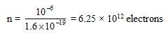
Ex.1 How many electrons constitute current of one micro ampere ?
Sol. Given : Current, 1 = 1µA = 10–6 A
We know, Q = ne
Where n is the number of electrons and e is the charg on 1 electron and e = 1.6 × 10⁻¹⁹ C
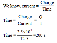
Ex.2 A battery can supply a charge of 2.5 × 10³ C. If the current is drawn from the battery at a rate of 12.5 A. Calculate the time in which battery will get discharged ?
Sol. Given : Charge, Q = 2.5 × 10³ C
Current, I = 12.5 A
A bulb connected to an electric cell
- Books Name
- Class 6 Science Book
- Publication
- PathSet Publications
- Course
- CBSE Class 6
- Subject
- Science
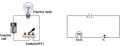
A Bulb connected to an electric cell
A Bulb Connected to an Electric Cell

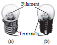
Filament: In an electric bulb, there is a thin tiny wire inside the glass cover. This is called a filament.

Terminal: All types of electric cells have two terminals:
- a positive terminal
- a negative terminal

Wire :
- An electric wire is a conducting path in an electric circuit, through which current flows.
- It is usually made out of a metal that is a good conductor of electricity.

Electric Bulb and its Working:

- It consists of a thin wire that glows due to the passage of current. This is known as the filament.

- An electric circuit provides a closed path for the current to flow. The terminals of the bulb are connected by wires to the electric cell.
- Sometimes the bulb does not glow as the filament gets fused (breaks) due to overheating.
An electric circuit
- Books Name
- CBSE Class 6 Science Book
- Publication
- Param Publication
- Course
- CBSE Class 6
- Subject
- Science
ELECTRIC CIRCUIT
The path of flow of electricity starting from one terminal of cell and returning to the other is called an electrical circuit. It consists of conducting wires and other resistances (like lamps etc.) between the terminals of a battery, along which an electric current flows.
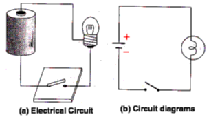
(a) Open Electric Circuit : An electric circuit through which no electric current flows is known as open electric circuit. The electric circuit will be open circuit if the plug of the key is taken out or if the connecting wires break from any point.
(b) Closed Circuit : An electric circuit through which electric current flows continuously is known as closed circuit.
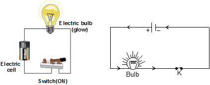
* For flow of electricity, the circuit must be made of conductors. Insulators in the path of electrical circuits makes the circuit incomplete.
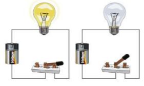
Ex.3 Look at the circuit given in figure (a) and figure (b). Read the instructions in each case and answer the questions given.
I. Which bulb B1/B2 in figure (a) will glow when
(a) only K1 is closed ?
(b) K1 and K2 are closed ?
(c) K1, K2 and K3 are closed ?
(d) only K2 and K3 are closed ?
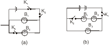
Sol. (a) No bulb will glow, (b) Bulb B1 will glow, (c) B1 and B2 both will glow and (d) No bulb will glow.
II. Which bulb B1/B2/B3 in figure (b) will glow when
(a) only K1 is closed ?
(b) only K2 is closed ?
(c) both K1 and K2 both are closed ?
Sol. (a) Bulb B3 will glow, (b) No bulb will glow and (c) All will glow.
An electric circuit
- Books Name
- Class 6 Science Book
- Publication
- PathSet Publications
- Course
- CBSE Class 6
- Subject
- Science
An Electric circuit

An Electric Circuit
An electrical circuit is a simplified representation of an electric circuit element.
Consider an electric cell and a bulb. The terminals of the cell are connected to the terminals of the bulb by the means of electric wires. Such an arrangement of cell and bulb is called an Electric Circuit.
- The circuit is said to be complete in this case because of which electricity will flow and the bulb will glow.
- This uses standard symbols for the components in the circuit and does not show the physical arrangements of the components.
- At present, our daily life on the earth has become nearly impossible without electricity. Homes to big industries depend on electricity.
- Electric current flows in a closed circuit loop. It is a closed-loop in which continuous electric current goes from the supply to the load equipment.
- A closed-loop path, which the current takes is known as an electric circuit.
- When the path of the circuit is closed, current flows through it.
- When there is a break in the path (switch is open) then, the circuit is open and not conducting so the current does not flow.
- One should be careful while setting up an electric circuit. It should be done under supervision.
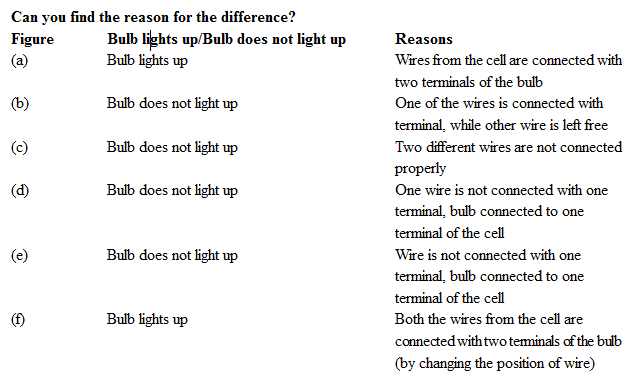
Electric Switch
- Books Name
- CBSE Class 6 Science Book
- Publication
- Param Publication
- Course
- CBSE Class 6
- Subject
- Science
Light Bulb Anatomy
A light bulb is a relatively simple device consisting of a filament resting upon or somehow attached to two wires. The wires and the filament are conducting materials that allow charge to flow through them. One wire is connected to the ribbed sides of the light bulbs. The other wire is connected to the bottom base of the light bulb. The ribbed edge and the bottom base are separated by an insulating material that prevents the direct flow of charge between the bottom base and the ribbed edge. The only pathway by which charge can make it from the ribbed edge to the bottom base or vice versa is the pathway that includes the wires and the filament. Charge can either enter the ribbed edge, make the pathway through the filament and exit out the bottom base; or it can enter the bottom base, make the pathway through the filament and exit out the ribbed edge. As such, there are two possible entry points and two corresponding exit points.
The successful means of lighting the bulb as shown above involved placing the bottom base of the bulb on the positive terminal and connecting the ribbed edge to the negative terminal using a wire. Any charge that enters the light bulb at the bottom base exits the bulb at the location where the wire makes contact with the ribbed edge. The second arrangement that lead to a lit light bulb involve placing the bulb at the negative terminal of the cell. A wire must then connect the other part of the bulb to the positive terminal of the cell.
Conductors and Insulators
(i) Conductors : Those substances through which electric charges can flow, are called conductors.
Example : silver, copper and aluminium etc.
(ii) Insulators : The material in which there is no flow of current are called insulators.
Example : Plastic, rubber and wood etc.
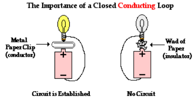
The Requirement of a Closed Conducting Path
There must be a closed conducting path that extends from the positive terminal to the negative terminal. It is not enough that there is simply a closed conducting loop; the loop itself must extend from the positive terminal to the negative terminal of the electrochemical cell. An electric circuit is like a water circuit at a water park. The flow of charge through wires is similar to the flow of water through the pipes and along the slides at a water park. If a pipe gets plugged or broken such that water cannot make the complete path through the circuit, then the flow of water will soon cease. In an electric circuit, all connections must be made and made by conducting materials capable of carrying charge. As the cell, bulb and wire experiment continues, some students explore the capability of various materials to carry a charge by inserting them in their circuit. Metallic materials are conductors and can be inserted into the circuit to successfully light the bulb. On the other hand, paper and plastic materials are typically insulators and their insertion within the circuit will hinder the flow of charge to such a degree that the current ceases and the bulb no longer lights. There must be a closed conducting loop from the positive to the negative terminal in order to establish a circuit and to have a current.
Electric Switch
- Books Name
- Class 6 Science Book
- Publication
- PathSet Publications
- Course
- CBSE Class 6
- Subject
- Science
An Electric Switch
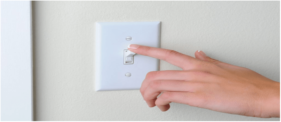
Electric Switch
- Switch is an integral part of an electric circuit. It is a simple device which breaks or completes a circuit.
- Electric switch is a simple device that either breaks the circuit or completes it to stop or start the flow of current
- When the switch is connected, we call it ON, and when it’s not in contact (or open) with the circuit, the switch is OFF

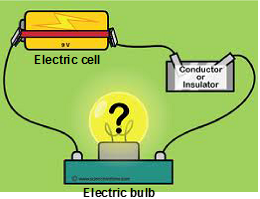
Electric conductors and insulators
- Books Name
- CBSE Class 6 Science Book
- Publication
- Param Publication
- Course
- CBSE Class 6
- Subject
- Science
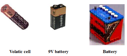
Electrical cells
Electrical cells are the sources of electric current.
(a) Types of electrical cell : (i) primary (ii) secondary
(i) Primary Cells : The cells which cannot be charged again and again are known as primary cells.
Example : Voltaic, Daniel, laclanche and dry cells.
(ii) Secondary Cell : The cells which can be charged again and again are known as secondary cells.
Example : Edison cell, lead-acid accumulator
* Note : combination of cell is known as battery.
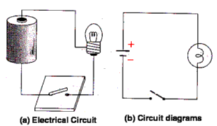
Circuit diagrams and circuit symbols
Scientists use certain symbols to draw electrical circuits. An electrical circuit drawn using these symbols is called a circuit diagram. The symbols used to indicate different components are called circuit symbols. Figure shows some components and their circuit symbols.
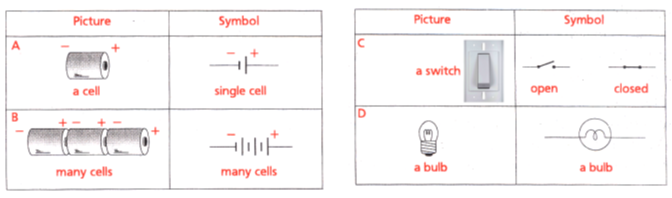
An electrical circuit in symbols :
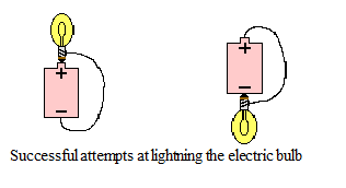
Requirements of a Circuit
Suppose that you were given a small light bulb, an electrochemical cell and a bare copper wire and were asked to find the four different arrangements of the three items that would result in the formation of an electric circuit that would light the bulb.
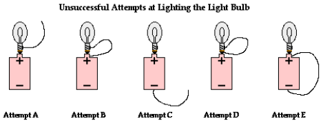
4 different attempts
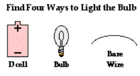
In attempt A, the wire does not loop back to the negative terminal of the cell. In attempt B, the wire does form a loop but not back to the negative terminal of the cell. In attempt C, there is no complete loop at all. Attempt D resembles attempt B in that there is a loop but not from the positive terminal to the negative terminal. And in attempt E, there is a loop and it does go from positive terminal to negative terminal; this is a circuit but the light bulb is not included as part of it.
Electric conductors and insulators
- Books Name
- Class 6 Science Book
- Publication
- PathSet Publications
- Course
- CBSE Class 6
- Subject
- Science
Electric Conductors and Insulators
Conductors - Materials that allow electricity to flow through them easily.
Insulators - Materials that do not allow electricity to pass through them.
- Human body is a conductor, so touch a current carrying wire is detrimental and so insulating it prevents from an electric shock.
- Some examples of conductors are: Metals like copper, Iron
- Some examples of insulators are: Rubber, Plastic
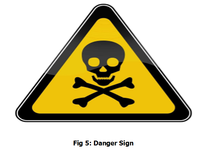
This sign is used in areas which are near electric junctions as a warning.
Electrical Safety
Electricity can be very dangerous if you do not handle electrical devices carefully. One should never play with electrical wires and sockets. Electricity from cells is safe and you can experiment with it, but you have to be careful not to connect the two terminals of a cell directly through a wire/conductor. Electricity generated by portable generators is dangerous and should not be used for experiments.
A demo video link to understand the working of Electric Circuit
https://youtu.be/GMS6SUYqsMM
Conclusion:
- Source of electric current: A device that can be used to produce an electric current is called a source of electric current.
- Electric circuit: A path for an electric current to flow is called an electric circuit.
- Closed-circuit: A circuit that has an ‘unbroken path’ through which an electric current can flow is called a closed circuit.
- Open circuit: A circuit with a break in it is called an open circuit.
- Electric switch: A device that is used to open or close a circuit is called an electric switch.
- Conductor (in this chapter): A material that allows electric current to pass through it easily is called a conductor.
- Insulator (in this chapter): A material that does not allow an electric current to pass through it easily is called an insulator.
- In a dry cell, a chemical reaction takes place to produce an electric current.
- A dry cell contains solid or semisolid ingredients.
- All cells have two terminals: the positive and the negative terminal.
- Electric current flows only if there is an unbroken or complete path, starting from one terminal of the source, through various devices back to the other terminal of the source.
- An electric switch is a device that is used to open or close a circuit.
- Safety is important while using electricity.
Electric Tester (Part -1)
- Books Name
- CBSE Class 6 Science Book
- Publication
- Param Publication
- Course
- CBSE Class 6
- Subject
- Science
Electric Tester
An electric tester consists of an electric cell, a torch bulb fitted in a holder and some connecting copper wires. The material to be tested is connected to the gap, left between the ends A and B of the connecting wires. If the bulb lights up at once, the given material is a conductor. If the bulb does not light up at all, the given material is an insulator .
Checking An Electric Tester:
We need to check the electric tester before we conduct any activity or experiment .Join the free ends of the tester together for a moment . This completes the circuit of the tester and the bulb should glow. However, if the bulb does not glow, it means that the tester is not working the possible reasons are :
Reason 1 : Connections are loose ,Check that all the connections are tight.
Reason 2 : The bulb is fused , Replace the bulb with another new bulb.
Reason 3 : The cell is used up , Replace the cell with a fresh one.
Modifications In Electric Tester :
The bulb glows when the electric current passes through an electric tester .When the current passes through the bulb due to the heating effect of current , the filament of the bulb gets heated to a high temperature and it starts glowing. However, if the current through a circuit is too weak, the filament does not get heated sufficiently and it does not get heated sufficiently and it does not glow. So, we may use an LED in place of the electric bulb in the tester.
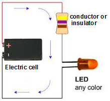
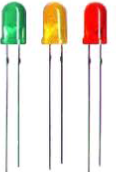
An LED means a light emitting diode. It is similar to a bulb but it runs on very low voltages. LED glows even when a weak electric current flows through it The coloured lights that you see in retail stores, stages, bridges and even in the keypads of mobile phones are all LEDs.
There are two wires (called leads) attached to an LED. One lead is slightly longer than the other while connecting to a circuit the longer lead is always connected to the positive terminal of the battery and the shorter lead is connected to the negative terminal of the battery.
When a standard bulb in the electric tester is replaced by LED, it can easily detect even a weak electric current in a circuit.
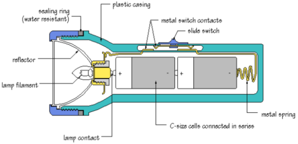
How Does an Electric Torch Work ?
An electric torch has one or more dry cells inside, which act as the source .These cells are connected through a switch to a small bulb. When the switch is pushed to the ‘on’ position, the circuit is complete and the bulb glows. When the switch is pushed to the ‘off’ position , the circuit is incomplete (broken).
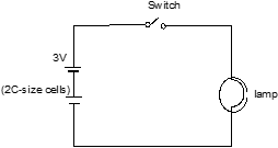
Circuit diagram of torch :
There are two electric cells a switch and a lamp the torch bulb. The lines in the diagram represent the metal conductors which connect the system together.
A circuit is a closed conducting path. in the torch, closing the switch completes the circuit and allows current to flow.
Extended Learning – Activities and Projects
Electric Tester (Part -2)
- Books Name
- CBSE Class 6 Science Book
- Publication
- Param Publication
- Course
- CBSE Class 6
- Subject
- Science
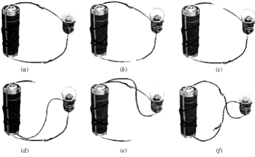
1. Phenomenon of torch bulb and its inside view.
Take a torch and look inside its bulb. You can also take out the bulb with the help of your teacher. What do you notice? Do you find a thin wire fixed in the middle of the glass bulb in figure (b)? Now switch the torch on and observe which part of the bulb is glowing.
The thin wire that gives off light is called the filament of the bulb. The filament is fixed to two thicker wires, which also provide support to it, as shown in figure (b). One of these thick wires is connected to the metal case at the base of the bulb in figure (b). The other thick wire is connected to the metal tip at the centre of the base. The base of the bulb and the metal tip of the base are the two terminals of the bulb. These two terminals are fixed in such a way that they do not touch each other. The electric bulbs used at home also have a similar design. Thus, both the electric cell and the bulb have two terminals each.
2. Phenomenon of cell and bulb with different arrangment.
Take four lengths of electric wire with differently coloured plastic coverings. Remove a little of the plastic covering from each length of wire at the ends. This would expose the metal wires at the ends of each length. Fix the exposed parts of two wires to the cell and the other two of the bulb as shown in figure A and B.
(A) Electric cell with two wires attached to it
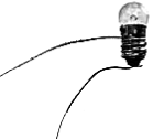
(B) Bulb connected to two wires
You can stick the wires to the bulb with the tape used by electricians. Use rubber bands or tape to fix the wires to the cell.
Now, connect the wires fixed to the bulb with those attached to the cell in six different ways as have been shown in figure C [(a) to (f). For each arrangement, find out whether the bulb glows or not. Write 'Yes' or 'No' for each arrangement in your notebook.
Now, carefully look at the arrangements in which the bulb glows. Compare these with those in which the bulb does not glow.
(C)
3. How to make a switch at home.
You can make a switch using two drawing pins, a safety pin (or a paper clip), two wires and a small sheet of thermo Col or a wooden board. Insert a drawing pin into the ring at one end of the safety pin and fix it on the thermo Col sheet. Make sure that the safety pin can be rotated freely. Now, fix the other drawing pin on the thermo Col sheet in a way that the free end of the safety pin can touch it. The safety pin fixed in this way would be your switch in this activity. Now, make a circuit by connecting an electric cell and a bulb with this switch. Rotate the safety pin so that its free end touches the other drawing pin.
The safety pin covered the gap between the drawing pins when you made it touch two of them. In this position the switch is said to be 'on' . Since the material of the safety pin allows the current to pass
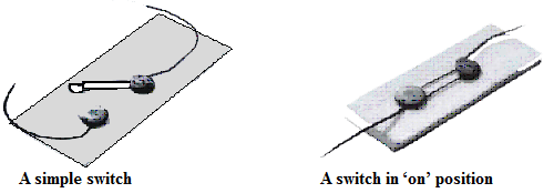
through it, the circuit was complete. Hence, the bulb glows. On the other hand, the bulb did not glow when the safety pin was not in touch with the other drawing pin. The circuit was not complete as there was a gap between the two drawing pins. In this position, the switch is said to be 'off' as in figure. A switch is a simple device that either breaks the circuit or completes it. The switches used in lighting of electric bulbs and other devices in homes work on the same principle although their designs are more complex.
4 How to check the material is conducting or non-conducting.
Would the bulb glow after completing the circuit shown, if instead of safety pin we use an eraser and key?
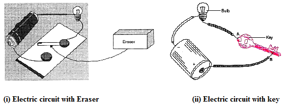
(i) No, the bulb will not light up. This is because an electric bulb lights up only when circuit is completed and eraser is a non-conducting material.
(ii) Yes, the bulb will light up. This is because an electric bulb lights up only when circuit is completed and key is a conducting material which completed the electric circuit.
Let Us Recapitulate
- Books Name
- CBSE Class 6 Science Book
- Publication
- Param Publication
- Course
- CBSE Class 6
- Subject
- Science
Let Us Recapitulate
1. Power station: Electricity that we uSe at homes, in our factories, is supplied from a power station.
2. Electric cell: Electric cell is a source of electricity.
3. Production of electricity in a cell: An electric cell produces a small amount of electricity from chemicals stored inside it. When the chemicals in the electric cells are used up, the electric cells stop I, producing electricity.
4. Terminal: All types of electric cells have two terminals, a positive terminal and a negative terminal. In a dry cell used in our homes, the central carbon rod is the positive (+) terminal and the zinc contained is the negative (–) terminal.
5. Battery: When two or more cells are joined together, the combination is called a battery.
6. Bulb: We get light from a thin tiny wire inside the glass cover. This is called filament. It is supported by two thicker wires. One of these thick wires is connected to the metal casing around the base of the bulb. The other is connected to the metal tip of the base. The base of the bulb and the metal tip ofthe base are the two terminals of the bulb. These two terminals are fixed in such a way that they do not touch each other.
The inside portion of the bulb is filled up with inert gases, like argon.
7. Circuit: The complete path, from one terminal of the electric cell through the bulb and back to the other terminal of the electric cell, is called a circuit. Open circuit: If there is any gap in the path of a circuit, the bulb does not light up. Such a circuit is called an open circuit.
Closed circuit: The bulb lights up only when a bulb and wire fonn a complete path, which starts at one terminal of electric cell and ends at the other terminal. Such a circuit is called a closed circuit.
8. Flow of current in a circuit: As soon as the path from one terminal of electric cell to the other is completed, an electric current starts flowing through the circuit and the bulb lights up. The electric current flows from the positive terminal of the electric cell to its negative terminal.
9. In the bulb, current enters through one of its terminals, flows through the filament. InsIde the bulb and comes out through the other terminal of the bulb. When the current flows through the filament, it starts glowing.
10. Fused bulb: Ifthe filament of the bulb is broken, the circuit is not completed and hence the current cannot flow. The bulb with broken filament is called a fused bulb. When a bulb gets fused, it does not light up.
11. Electric switch: Electric switch is a simple device that either breaks the circuit or completes it to stop or start the flow of current.
(i) When the switch completes the circuit, it is called closed switch.
(ii) When the switch breaks the circuit, it is called open switch.
12. Conductors
(i) Materials through which electric current can flow are called conductors.
(ii) Most metals are conductors.
(iii) Our body is also a good conductor.
13. Insulators
(i) Materials, through which the electric current cannot pass, are called insulators. In other words, insulators are-the bad conductors of electricity.
(ii) Rubber and wood are insulators.
14. Conduction tester: It is a simple device to test whether a material is a conductor or insulator.
15. Filament: The thin wire that gives off light is called the filament of the bulb.
16. Dry cell: Dry cell is a source of electricity. It generates direct current (DC) due to chemical reaction that takes place inside it.
Keywords
1. Bulb: An electric bulb is a device which glows and emits light, when electric current is passed through it.
2. Conductors: Materials that allow electric current to pass through them are called conductors.
3. Electric cell: Electric cell is a source of electricity.
4. Electric circuit: The complete path from one terminal of the electric cell through the bulb and back to other terminal of the electric cell is called an electric circuit.
5. Filament: In electric bulb, there is a thin tiny wire inside the glass cover. This is called filament.
6. Insulator: Materials that do not allow electric current to .pass through them are called insulators.
7. Switch: Electric switch is a simple device that either breaks the circuit or completes it to stop or start the flow of current.
8. Terminal: All types of electric cells have two terminals, a positive terminal and a negative terminal.