 Param Publication
 ReginaTagebücher
- Books Name
- Class 6 Mathematics Book
- Publication
- ReginaTagebücher
- Course
- CBSE Class 6
- Subject
- Mathmatics
Chapter 14
Practical Geometry
Introduction to geometrical tools
Geometric tools are the instruments used to draw different types of geometric shapes. To draw these shapes, there are different types of tools with different names used while solving problems based on geometry. Different figures have characteristic properties such as length, breadth, diameter, etc. which set them apart from one another and are parameters to produce the figures on paper. Practical geometry or Euclidean geometry is the most pragmatic branch of geometry that deals with the construction of different geometrical figures using geometric instruments such as rulers, compasses, and protractors.
The early geometer studied figures such as points, lines, and angles that required the use of rulers and compasses only. With the advent of more geometric designs, other geometric tools were invented. Some of the most commonly used geometric tools are:
- Ruler
- Compass
- Protractor
- Divider
- Set-squares
Introduction to circles
Circle is the set of points central from a given point. The distance from that point to the circle is called the radius of the circle .The point from which all the points on a circle are in middle is known as the center of the circle.
A circle is named with a single letter, its center
Construction of a circle,

The circle above has its center at point C and a radius of length r. By definition, all radii of a circle are congruent, since all the points on a circle are the same distance from the center, and the radii of a circle have one endpoint on the circle and one at the center.
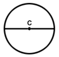
All circles have a diameter, too. The diameter of a circle is the segment that contains the center and whose endpoints are both on the circle. The length of the diameter is twice that of the radius. Therefore, all diameters of a circle are congruent, too.
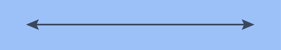
Introduction to line segments
This is a line! It has no endpoints and extends endlessly in both directions.
If you mark two points A and B on it and pick this segment separately, it becomes a line segment
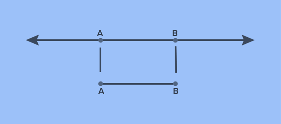
This line segment has two endpoints A and B whose length is fixed. The length of this line segment is the distance between its endpoints A and B.
So, a line segment is a piece or part of a line having two endpoints. Unlike a line, a line segment has a definite length.

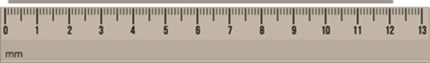
The length of a line segment can be measured either in metric units such as millimetres, centimetres, or customary units like feet or inches.
Copying an existing line segment
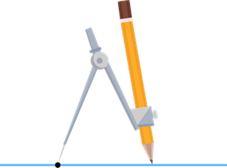
The key to copying a given line segment is to open your compass to the length of the segment; then, using that amount of opening, you can mark off another segment of the same length.
Step 1: Place one end of the compass on one end of the line segment and the other end of the compass on the other end of the line segment.

In the figure given above, AB¯¯¯¯¯¯ is being copied using a compass.
Step 2: Now draw a new line on the sheet of paper.
Step 3: By keeping the measurement obtained using the compass intact, place the pointy end of the compass anywhere on the line and draw an arc over the line using the pencil end.
Step 4: The point on the line where the pointy end was placed becomes one end of the line segment, while the point where the arc and the line meets becomes the other end of the line segment.

Using the same measurement of AB¯¯¯¯¯¯, CD¯¯¯¯¯¯ is formed.
In other words, AB¯¯¯¯¯¯=CD¯¯¯¯¯¯
If the arc does not fall over the line segment, keep extending the line until it meets the arc at some point.
Introduction to perpendiculars to a line segment
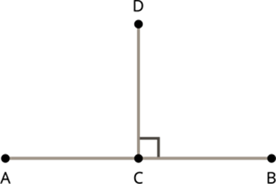
When line segment AB¯¯¯¯¯¯ meets CD¯¯¯¯¯¯ at right angles, then the line segments AB¯¯¯¯¯¯ and CD¯¯¯¯¯¯ are said to be perpendicular.
When two line segments meet at right angles to each other, then the two line segments are said to be perpendicular to each other.
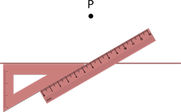
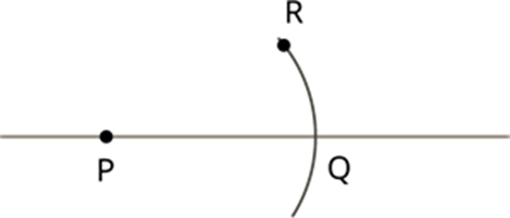
Perpendicular to a line without a point on it,
A perpendicular to a line can also be drawn without a point on it.
Let us look at how to do that.
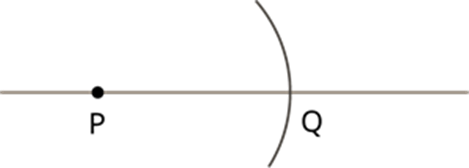
Construction using rulers and set squares
Step 1: Draw a line using a ruler on the sheet of paper.

Step 2: Place a point P anywhere on the sheet.

Step 3: Place the set square on the line such that the arm having 90∘ lies on the line.
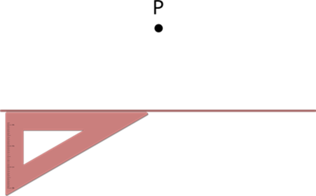
Step 4: Place a ruler on the other side of the set square.
tep 5: While holding the ruler firmly, slide the set square until the other arm of the set square touches the point P.
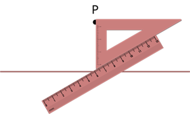
Step 6: Now draw a line from P until it meets the line already drawn at Q.
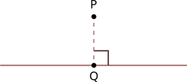
Construct a perpendicular bisector
Bisecting means dividing a line segment into two equal parts.
Perpendicular bisector:
When a line segment is divided into two halves by a perpendicular line segment, then the perpendicular line segment becomes the perpendicular bisector.

In the figure given above, CD¯¯¯¯¯¯¯ is the perpendicular bisector of AB¯¯¯¯¯¯
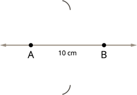
Make a note of the following steps to construct a perpendicular bisector of the line segment AB=10cm.
Step 1: Draw a line and mark two points A and B on it. That is, AB=10cm.
![]()
Step 2: Make A as centre and radius more than half of the length of AB, draw two arcs of same length, one above AB and one below AB.
Step 3: Now take B as centre, draw two arcs with the same radius to cut the arcs drawn in step 2. Mark the points of intersection of the arcs as C and D.
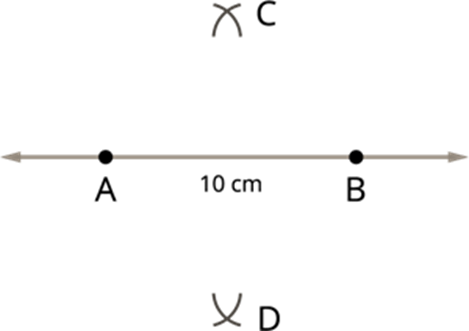
Step 4: Then, join C and D. The line CD will intersect AB. Mark the point of intersection as O. CD is the required perpendicular bisector of AB. Now measure the distance between A and O and O and B. We have AO=OB =5cm.

Thus, we have constructed the perpendicular bisector of AB and this perpendicular bisector divides the line AB=10cm into two parts, such that AO =OB =5cm.
Introduction to angles,
Angle:
When two lines meet, they always meet at a certain angle. An angle is specified using a number followed by a (∘) symbol like 15∘, 120∘, 180∘, and so on.
Example:
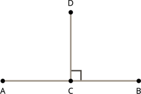
In the figure given above, CD¯¯¯¯¯¯¯ meets CB¯¯¯¯¯¯ at 90∘
An angle can be constructed by using a protractor.
Let us see how to construct a an using a protractor.
Step 1: Draw a line segment PA.
![]()
Step 2: Place the protractor on the line segment PA by taking the midpoint of the protractor at point P, as shown in the figure.
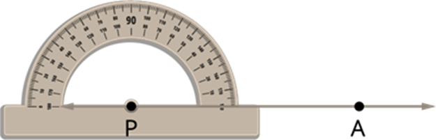
Step 3: On PA from the right, start counting from 0° in the ascending order (counter-clockwise direction and finally mark a point Q using a sharp pencil at the point showing 60° on the semi-circular edge of the protractor.
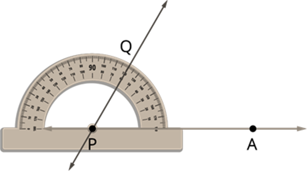
Step 4: Remove the protractor and join PQ.
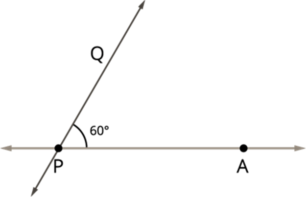
We get the required angle, ∠APQ= 60°.
Copying an angle
Angles of unknown measurements can be copied using compasses.
Let us see how to copy an angle of unknown measure.
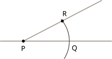
Copying an angle of unknown measure
Step 1: Draw a line on an empty sheet of paper.

Step 2: Consider the already existing angle formed by joining two different lines.
Step 3: With A as centre, draw an arc such that the arc cuts both the lines at B and C.
Step 4: Keeping the measurements of the arc drawn intact, place a point P on the line and with P as centre construct an arc such that the arc meets the line at Q.
Step 5: Similarly, after measuring the distance between B and C using a compass, with Q as centre place the point R on the arc.
Step 6: Join the points P and R to form the copied angle.
Angle bisector of an angle
The angle bisector is formed when a line or line segment divides an angle into two equal parts.
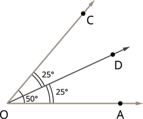
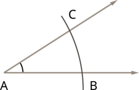
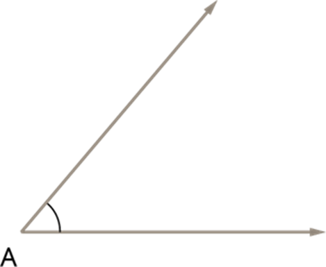
Follow the below steps, construct the bisector of the ∠A with the measure 60°.
Step 1: Draw the given angle ∠A with the measure 60° using the protractor.
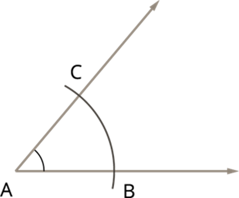
Step 2: Taking A as centre and convenient radius, draw an arc to cut the two lines such that the arc meets the lines at B and C.
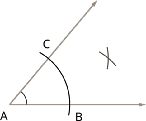
Step 3: With the same radius and B as centre, draw an arc, and with C as centre and with the same radius, cut the already drawn arc.
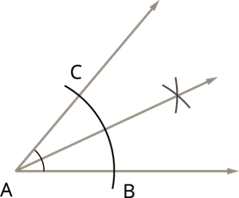
Step 4: Join A and the point of intersection of the arcs to form the angle bisector.
Construction of special angles
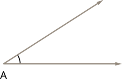
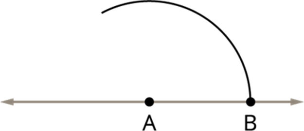
i) Construction of 60° angle:
Step 1: First draw a straight line, and mark a point A on it.
![]()
Step 2: Take the point A as centre, draw an arc of convenient radius to the line to meet at a point B.
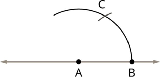
Step 3: With the same radius, take B as centre, draw an arc to cut the previous arc at C.
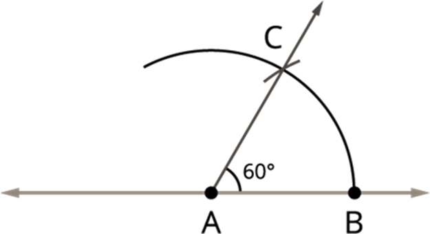
Step 4: Join AC. Then ∠BAC is the required angle with the measure 60°.
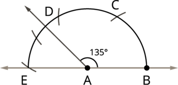
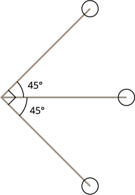
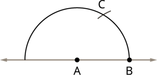
ii) Construction of 135° angle:
Step 1: First draw a straight line, and mark a point A on it.
![]()
Step 2: Take the point A as centre, draw an arc as below which meet at a point B.
Step 3: Take radius, and draw an arc for 60°, as shown above. This cuts an arc at point C.
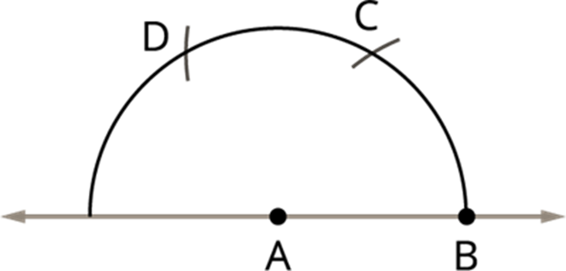
Step 4: Now take C as centre, draw an arc to with the same radius, point it as D. Here the point D gives the angles of 120°.
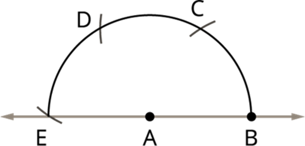
Step 5: With the same radius, draw an arc from the point D that cuts the E which gives the 180°.
Step 6: Finally, draw the angle bisector between the two points D (120°) and E (180°). The angle bisector separates the two points D and E and gives the angle 150°.
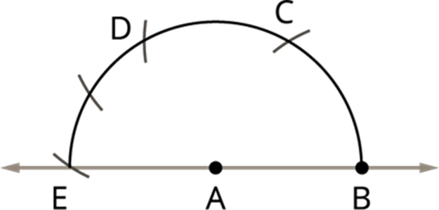
Step 7: Now again find the angle bisector between 150° and 120°, the resultant gives the required angle 135°.