 Grow Career Publication
1.Reflection of Light by Spherical Mirrors
- Books Name
- Physics Book Part l and ll
- Publication
- Grow Career Publication
- Course
- CBSE Class 12
- Subject
- Physics
Chapter 9: Ray optic and optical instrument
Reflection of Light by Spherical Mirrors
Reflection of Light
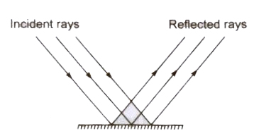
When light is incident on a surface, it is sent back by the surface in the same medium through which it had come called as ‘reflection of light’ by the surface.
Laws of Reflection
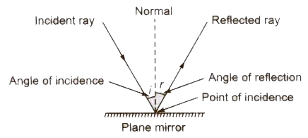
There are two laws of reflection.
- The incident ray, the reflected ray and the normal at the point of incidence all three lie in the same plane.
- The angle of incidence (i) is always equal to the angle of reflection .
Types of Reflection
- Regular Reflection When a parallel beam of reflected light rays is obtained for a parallel beam of incident light rays after reflection from a plane reflecting reflection is called regular reflection.
- Irregular or Diffused Reflection When a non-parallel beam of reflected light rays is obtained for a parallel beam of incident light rays after reflection from a surface, then such type of reflection is called irregular or diffused reflection.
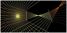
Reflection of Spherical Mirror
- A spherical mirror is a part cut from a hollow sphere.
- The reflection at spherical mirror also takes place in accordance with the laws of reflection.
Sign Convention
All distances are measured from the pole of the mirror & the distances measured in the direction of the incident light is taken as positive.
(i) The distance measured against the direction of the incident light are taken as negative.
Focal Length of a Spherical Mirror
Distance between the focus and the pole of the mirror is called focal length of the mirror and is denote by f.
b) The focal length of a concave mirror is negative and that of a convex mirror is positive.
c) The focal length of a mirror (concave or convex) is equal to half of the radius of curvature of the mirror, i.e., f = .
Principal Axis of the Mirror: The straight line joining the pole and the centre of curvature of spherical mirror extended on both sides is called principal axis of the mirror.
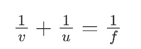
Mirror Formula:
Where u = distance of the object from the pole of mirror
V = distance of the image from the pole of mirror
F = focal length of the mirror
Where R is the radius of curvature of the mirror.
Magnification: It is defined as the ratio of the size of the image to that of the object.
Luminous Objects
The objects which emits its own light, are called luminous objects, e.g., sun, other stars, an oil lamp etc.
Non-Luminous Objects
The objects which do not emit its own light but become visible due to the reflection of light falling on them, are called non-luminous objects, e.g., moon, table, chair. Trees etc.
Ray of Light
A straight line drawn in the direction of propagation of light is called a ray of light.
Beam of Light A bundle of the adjacent light rays is called a beam of light.
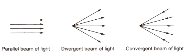
Image If light ray coming from an object meets or appear to meet at a point after reflection or refraction, then this point is called image of the object.
Real Image The image obtained by the real meeting of light rays, is called a real image.
Real image can be obtained on a screen. Real image is inverted.
Virtual Image The image obtained when light rays are not really meeting but appears to meet only, is called a virtual image.
Types of Reflection
(i) Regular Reflection When a parallel beam of reflected light rays is obtained for a parallel beam of incident light rays after reflection from a plane reflecting reflection is called regular reflection.
(ii) Irregular or Diffused Reflection When a non-parallel beam of reflected light rays is obtained for a parallel beam of incident light rays after reflection from a surface, then such type of reflection is called irregular or diffused reflection.

Mirror
A smooth and highly polished reflecting surface is called a mirror.
(i) Plane Mirror A highly polished plane surface is called a plane mirror.
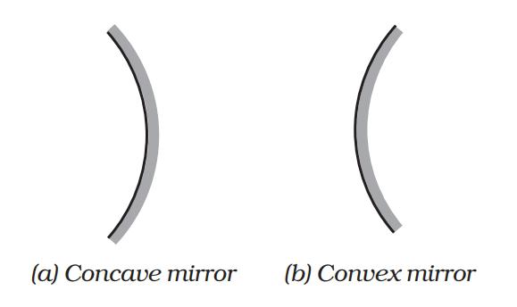
Spherical Mirror : A highly polished curved surface whose reflecting surface is a cut part of a hollows at glass sphere is called a spherical mirror. Spherical mirrors are of two types
- Concave Mirror A spherical mirror whose bent in surface is reflecting surface, is called a concave mirror.
- Convex Mirror A spherical mirror whose bulging out surface is reflecting surface, is called a convex mirror.
REFRACTION AT SPHERICAL SURFACES AND BY LENSES
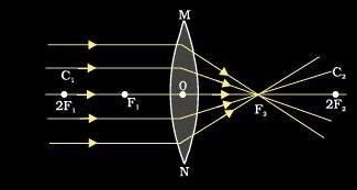
1. Focal length of a convex lens: The distance between the optical centre and principal focus of a lens is called focal length.Focal length of a lens depends on the refractive index of the glass and its curvature. In case of higher refractive index, focal length will be short.
A convex lens is also called converging lens as the parallel beam of light rays passing through it converges at a single point.
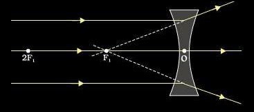
2. Focal length of concave lens:
The distance between optical centre and principal focus is called focal length of a concave lens.
Refraction at Spherical Surfaces
Consider refraction at a spherical interface between two transparent media. An infinitesimal part of a spherical surface can be regarded as planar and the same laws of refraction can be applied at every point on the surface.
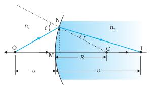
The rays are incident from a medium of refractive index n1, to another of refractive index n2.
Assuming the aperture (or the lateral size) of the surface to be small compared to other distances involved, so that small angle approximation can be made.
Consider NM will be taken to be nearly equal to the length of the perpendicular from the point N on the principal axis.
Considering small angles,
tan<NOM = (MN)/(OM)
tan < NCM = (MN/MC)
tan<NIM = (MN)/(MI)
Now, for ΔNOC, <i is the exterior angle. Therefore, i = ∠NOM + ∠NCM
i = (MN/OM)+(MN/MC) (equation (1))
Similarly, r = ∠NCM – ∠NIM
e., r = (MN/MC) – (MN/MI) (equation (2))
Now, by Snell’s law n1 sin i = n2 sin r or for small angles
n1i = n2r
Substituting i and r from Equation. (1) and (2), we get
(n1/OM) + (n2/MI) = (n2 – n1)/MC) Equation (3)
Here, OM, MI and MC represent magnitudes of distances. Applying the Cartesian sign convention,
OM = –u, MI = +v, MC = +R
Substituting these in Eq. (3), we get,
(n2 –v) –(n1/u) = (n2 – n1)/(R) Equation (4)
Equation (4) gives us a relation between object and image distance in terms of refractive index of the medium and the radius of curvature of the curved spherical surface. It holds for any curved spherical surface.
Refraction by Lens: Convex & Concave
A ray of light incident on the lens parallel to the principal axis after refraction passes through second principal axis.
A ray of light passing through first principal focus after refraction should move parallel to the principal axis.
A ray of light passing through the optical centre should go-undeviated after refraction.
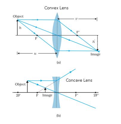
1. Magnification of a lens
It is the ratio of the size of the image to the size of the object.
It is denoted as m =(h’/h) = (v/u)
For a virtual and erect image is formed by a convex lens or by concave lens, m is positive and for real and inverted image m is negative.
Combination of thin lenses in contact
Let us consider two lenses A and B of focal length f1 and f2 placed in contact with each other. An object is placed at O beyond the focus of the first lens A on the common principal axis.
The lens A produces an image at I1 . This image I1 acts as the object for the second lens B. The final image is produced at I as shown in Fig. Since the lenses are thin, a common optical centre P is chosen.
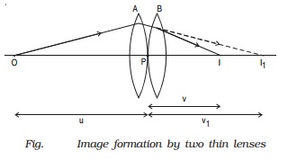
Let PO = u, object distance for the first lens (A), PI = v, final image distance and PI1 = v1, image distance for the first lens (A) and also object distance for second lens (B).
For the image I1 produced by the first lens A,
1/v1 ? 1/u = 1/f1 ????..(1)
For the final image I, produced by the second lens B,
1/v - 1/v1 = 1/f2 ????..(2)
Adding equations (1) and (2),
1/v ? 1/u = 1/f1 + 1/f2 ????..(3)
If the combination is replaced by a single lens of focal length F such that it forms the image of O at the same position I, then
1/v - 1/u = 1/F ????(4)
From equations (3) and (4)
1/F = 1/f1 + 1/f2 ?????(5)
This F is the focal length of the equivalent lens for the combination. The derivation can be extended for several thin lenses of focal
lengths f1, f2, f3 ... in contact. The effective focal length of the combination is given by
1/F = 1/f1 + 1/f2 + 1/f3 + ?????.. ?..(6)
In terms of power, equation (6) can be written as
P = P1 + P2 + P3 + .... ...(7)
Equation (7) may be stated as follows :
The power of a combination of lenses in contact is the algebraic sum of the powers of individual lenses.
2. Prism
- Books Name
- Physics Book Part l and ll
- Publication
- Grow Career Publication
- Course
- CBSE Class 12
- Subject
- Physics
Prism
A prism is a transparent medium bounded by the three plane faces. Out of the three faces, one is grounded and the other two are polished. The polished faces are called refracting faces. The angle between the refracting faces is called angle of prism, or the refracting angle. The third face is called base of the prism.
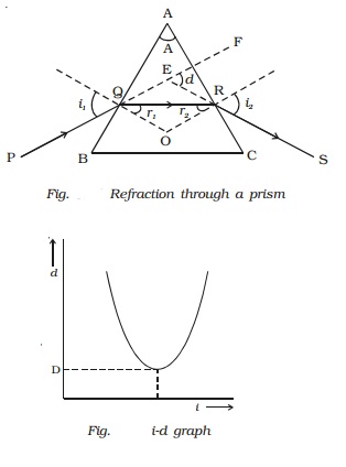
Refraction of light through a prism
Fig. shows the cross section of a triangular prism ABC, placed in air. Let ?A? be the refracting angle of the prism. A ray of light PQ incident on the refracting face AB, gets refracted along QR and emerges along RS. The angle of incidence and refraction at the two faces are i1, r1 , r2 and i2 respectively. The angle between the incident ray PQ and the emergent ray RS is called angle of deviation, d. In the ∆QER, the exterior angle FER = angle EQR + angle ERQ
d = (i1 - r1) + (i2 - r2)
d = (i1 + i2) - (r1 + r2) ????.(1)
In the quadrilateral AQOR, the angles at Q and R are right angles
Angle Q + Angle R = 1800
A + Angle R = 1800 ????.(2)
Also, from the ∆QOR
r1+ r2 = A ??????..(4)
Substituting in (1),
d = i1 + i2 - A
or A + d = i1 + i2 ...(5)
For a given prism and for a light of given wavelength, the angle of deviation depends upon the angle of incidence.
As the angle of incidence i gradually increases, the angle of deviation d decreases, reaches a minimum value D and then
increases. D is called the angle of minimum deviation. It will be seen from the graph (Fig. ) that there is only one angle of
incidence for which the deviation is a minimum.
At minimum deviation position the incident ray and emergent ray are symmetric with respect to the base of the prism. (i.e)the refracted ray QR is parallel to the base of the prism.
At the minimum deviation
i1 = i2 = i and r1 = r2 = r
from equation (4) 2r = A or r = A/2
and from equation (5) 2i = A + D or i = ( A+D )/2
The refractive index is ? = sin i/sin r
? = [sin((A+D) / 2)] / sin(A/2)
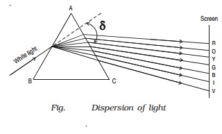
- Dispersion of light
Dispersion is the splitting of white light into its constituent colours. This band of colours of light is called its spectrum.
In the visible region of spectrum, the spectral lines are seen in the order from violet to red. The colours are given by the word VIBGYOR (Violet,Indigo, Blue, Green,Yellow, Orange and Red) (Fig. )
The origin of colour after passing through a prism was a matter of much debate in physics. Does the prism itself create colour in some
way or does it only separate the colours already present in white light?
Optical Instruments
- Optical instruments are instruments using reflecting and refracting properties of mirrors, lenses and prisms.
- A number of optical devices and instruments have been designed utilising reflecting and refracting properties of mirrors, lenses and prisms.
- Periscope, kaleidoscope, binoculars, telescopes; microscopes are some examples of optical devices and instruments.
- Some of optical instruments which consists of lenses and prisms are:-
1.Binoculars
2.Telescope
3.Microscope
4.Eye
1. Huygens Principle and Addition of Waves
- Books Name
- Physics Book Part l and ll
- Publication
- Grow Career Publication
- Course
- CBSE Class 12
- Subject
- Physics
Chapter 10: Wave optics

Huygens Principle and Addition of Waves
Defining the Huygens Principle
Huygens principle proposed by Christiaan Huygens In 1678 revolutionized our understanding of light and its characteristics. You may be familiar with the rectilinear theory of light that purports that light travels along straight paths. Huygens principle is one of the key methods for studying various optical phenomena. The principle is a method of analysis applied to problems of wave propagation both in the far-field limit and in near-field diffraction and also reflection.
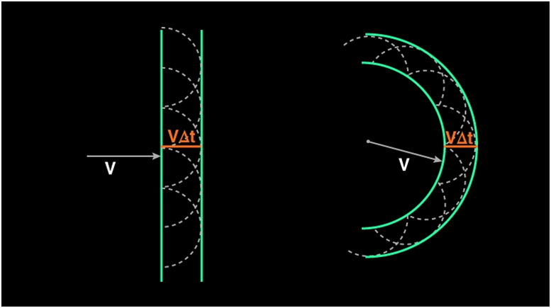
Primary and Secondary Sources
Huygens stated that light spread out like a wave along with all directions from a source. The locus of points that travelled some distance during a fixed time interval is called a wavefront. Thus, from a point source of light, the locus of points that light has travelled during a fixed time period is a sphere (a circle if you consider a 2D source).After the primary wavefront is created, a secondary wavefront is created from every primary wavefront. Secondly, every point on the wavefront acts as a secondary source of light that emits more wavefronts. The net effect is that the effective wavefront generated is tangential to all the secondary wavefronts generated by the secondary sources as shown in the figure.
Advantages:
- Huygens concept proved the reflection and refraction of light.
- The concepts like diffraction of light, as well as interference of light, were proved by Huygens.
Disadvantage:
- Concepts like emission of light, absorption of light and polarization of light were not explained by Huygens principle.
- Huygens principle failed to explain the photoelectric effect.
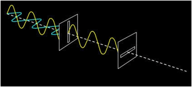
Reflection of a plane wave using Huygens Principle
As discussed earlier, when light is incident on the surface it is re- emitted without any change in the frequency. This re-emitted light which is returned into the same medium from which it comes out is called Reflection of Light. Consider the figure given below:
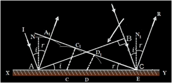
Imagine incoming rays are incident on a surface. Here the wavefronts are plane waves. In plane wavefront, the wavefronts will be infinite parallel planes to each other with constant amplitude. Consider the plane wave AB which falls on the reflecting surface. AB is the incident wavefront and is drawn as perpendicular to the incident ray. It falls at an angle I on the surface. Now according to the Huygens’s principle every point on AB act as a source of secondary wavelets. Consider the points A and B as new sources which emits the secondary waves. The velocity of the propagation of waves is ‘v’. Let ‘t’ be the time taken. So let’s assume that vt be the distance moved by the secondary wavelets. AA1 and BE are the secondary waves. Now the new wavefront should be a tangents line which connects those two secondary waves. The reflected waves should be perpendicular to the new wavefront. A1E is the new tangential line which connects the secondary wavelets.
Consider ΔABE and ΔAA1E. Here AE is common.
<B = <A1 = 90° .
AA1 = BE.
These triangles are congruent triangles
So <I = <r
Thus Angle of Incidence = Angle of Reflection. This is the first law of reflection.
The doppler effect
we should mention here that one should be careful in constructing the wave fronts if the source (or the observer) is moving. For example, if there Is no medium and the source moves away from the observer, then later wave fronts have to travel a greater distance to reach the observer and hence take a longer time. the time taken between the arrival of two successive wave fronts is hence longer at the observer than it is at the source. thus, when the source moves away from the observer the frequency as measured by the source will be smaller. this is known as the doppler effect.
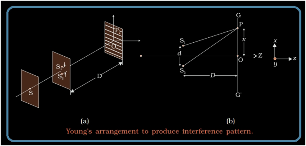
COHERENT AND INCOHERENT ADDITION OF WAVES
The sources and the waves are said to be coherent if they have the same frequencies, same wavelength, same speed, almost same amplitude and have no phase difference or a constant phase difference. If any of the properties is lacking, the sources are said to be incoherent.
The examples of the coherent sources and the waves are sound waves from two loud speakers driven by the same audio oscillator, electromagnetic waves from two microwaves horns driven by the same oscillator, light waves generated by Young double-slit experiment, light waves coming from a laser gun.
Let for any other arbitrary point the phase difference between the two displacements produced by the waves y1 and y2 be φ.
Thus, if the displacement produced by y1 is given by
y1=acos(ωt)
then, the displacement produced by y−2 would be
y2=acos(ωt+ϕ)
and the resultant displacement will be given by
y=y1+y2
y=a[cosωt+cos(ωt+φ)]
y=2acos(φ/2)cos(ωt+φ/2)
[∵cosA+cosB=2cos(A+B2)cos(A−B2)]
The amplitude of the resultant displacement is 2a cos (φ/2) and therefore the intensity at that point will be if the waves have the same intensity Io
I=4Iocos2(ϕ2)
If the waves are of different intensities, then the resultant intensity is given by
I = I1 + I2 + 2 √(I1 I2 Cos Θ), where Θ is the phase difference between two waves. For the constructive interference the value of Θ = 0°, so that the Cos Θ = 1 and for the destructive interference the value of Θ = 90°, so that the Cos Θ = 0.
In case of the incoherent sources or waves we can have the intensity simply by algebraic method that means I = I1 + I2.
Intensity of light at the point of Interference
We know that intensity of any light wave is directly proportional to the square of its amplitude. In case of coherent sources, let’s consider the factor of frequency to be a constant. Thus the intensity for the wave is considered as KA2.
I = KA2, where K is the constant which depends on what medium the wave is in.
Consider the resultant amplitude as ‘R’ at the point of interference. Now the resultant intensity at this point can be written as
IR = KR2
= K [A12 + A22 + 2A1 A2 Cos ϕ]
= KA12 + KA22+ 2KA1 A2 Cos ϕ
Substitute KA12 = I1 and KA22 = I2
Thus IR = I1 + I2 + 2 √(I1 I2 Cos ϕ)
So the resultant intensity of two waves after the interference phenomenon is
IR = I1 + I2 + 2 √(I1 I2 Cos ϕ)
Here ϕ is the phase difference between two waves.
In case of constructive interference, the value of ϕ =0 and so Cos ϕ =1.Then IR = I1 + I2 + 2 (√I1 I2 = (√ I1 + √I2)2 where the waves are superposed in same phase. Here the resultant intensity is maximum. For destructive interference, the waves superpose in opposite direction. Then Cos ϕ = -1 Thus the resultant intensity is minimum. So, IR = I1 + I2 - 2 √( I1 I2 = (√I1 - √I2)2.
Interference of equal Intensity waves
As mentioned earlier, the resultant intensity of waves at the point of interference
IR = (I1 + I2 + 2 √(I1 I2 Cos ϕ). Let us consider that the two waves have same and equal intensity, which means I1 = I2= I0.
Thus IR = 2I0 + 2I0 Cos ϕ
= 2I0 (1+ Cos ϕ)
1+ Cos ϕ = 2cos2 ϕ/2 (Cos ϕ in half angle form)
Then IR = 4I0 cos2 ϕ/2.
Hence for constructive interference, intensity will be maximum, IR = ( √I1 + √I2)2 = 4 I0.
For destructive interference, the intensity is minimum and IR = (√I1 - √I2)2 = 0.
Diffraction

If the wave travels at an angle theta,θ from the normal to the slit, then there is a path difference x,x between the waves produced at the two ends of the slit.
X, equals, a, sine, theta.
X=asinθ
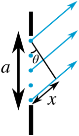
The path difference between the top and middle waves is then
x′=a/2sinθ
If the path difference between the top and middle waves is 2/λ, then they are exactly out of phase and cancel each other out. This happens to all consecutive pairs of waves (the ones produced by the second source from the top and the second source past the middle etc.) at this angle, so there is no resultant wave at this angle.
λ=asinθ
Now the slit can be divided into four equal sections and the pairing of sources to give destructive interference can be repeated for the top two sections, which is identical to the result of pairing off matching sources in the bottom two sections. In the case, we obtain for a minimum (since every pair of waves we consider will destructively interfere due to our choice of geometry and pairing),
λ/2=4asinθ
We can then divide the slit aperture into six equal sections, and pair off sources in the top two divisions, then the middle two divisions, and then the bottom two, to give destructive interference for every matched pair. The minima of intensity are obtained at anglesn, lambda,
N λ=a sin θ
where n,n is an integer n, equals, 0,n=0. There is a maximum of intensity in the centre of the pattern.
What is Polarization
In Physics, is defined as a phenomenon caused due to the wave nature of electromagnetic radiation. Sunlight travels through the vacuum to reach the Earth, which is an example of an electromagnetic wave. These waves are called electromagnetic waves because they form when an electric field that interacts with a magnetic field. In this article, you will learn about two types of waves, transverse waves, and longitudinal waves. You will also learn about polarization and plane polarised light.
Transverse waves
Transverse waves are waves, movement of the particles in the wave is perpendicular to the direction of motion of the wave. Longitudinal waves are when the particles of the medium travel in the direction of motion of the waves.
Light is the interaction of electric and magnetic fields travelling through space. The electric and magnetic vibrations of a light wave occur perpendicularly to each other. The electric field moves in one direction and magnetic in another though always perpendicularly. So, we have one plane occupied by an electric field, the magnetic field perpendicular to it, and the direction of travel which is perpendicular to both. These electric and magnetic vibrations can occur in numerous planes. A light wave that is vibrating in more than one plane is known as unpolarized light. The light emitted by the sun, by a lamp or a tube light are all unpolarised light sources. As you can see in the image below, the direction of propagation is constant, but the planes on which the amplitude occurs is changing.
1. Photoelectric Effect
- Books Name
- Physics Book Part l and ll
- Publication
- Grow Career Publication
- Course
- CBSE Class 12
- Subject
- Physics
Chapter 11: Dual nature of radiation and matter
Photoelectric Effect
ELECTRON EMISSION
However, the free electrons cannot normally escape out of the metal surface. If an electron attempts to come out of the metal, the metal surface acquires a positive charge and pulls the electron back to the metal. The free electron is thus held inside the metal surface by the attractive forces of the ions. Consequently, the electron can come out of the metal surface only if it has got sufficient energy to over come the attractive pull. A certain minimum amount of energy is required to be given to an electron to pull it out from the surface of the metal. One electron volt is the energy gained by an electron when it has been accelerated by a potential difference of 1 volt, so
That 1 eV = 1.602 ×10⁻¹⁹ J.

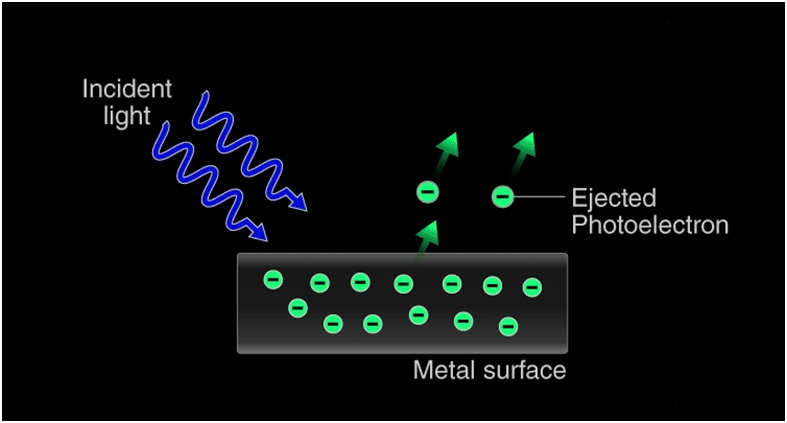
PHOTOELECTRIC EFFECT
The photoelectric effect occurs because the electrons at the surface of the metal tend to absorb energy from the incident light and use it to overcome the attractive forces that bind them to the metallic nuclei. An illustration detailing the emission of photoelectrons as a result of the photoelectric effect is provided below.
The Concept of Photons
The photoelectric effect cannot be explained by considering light as a wave. However, this phenomenon can be explained by the particle nature of light, in which light can be visualized as a stream of particles of electromagnetic energy. These ‘particles’ of light are called photons. The energy held by a photon is related to the frequency of the light via Planck’s equation:
![]()
Where,
E denotes the energy of the photon
H is Planck’s constant
![]()
C is the speed of light (in a vacuum)
Λ is the wavelength of the light
Therefore, the relationship between the energy of the photon and the kinetic energy of the emitted photoelectron can be written as.
![]()
![]()
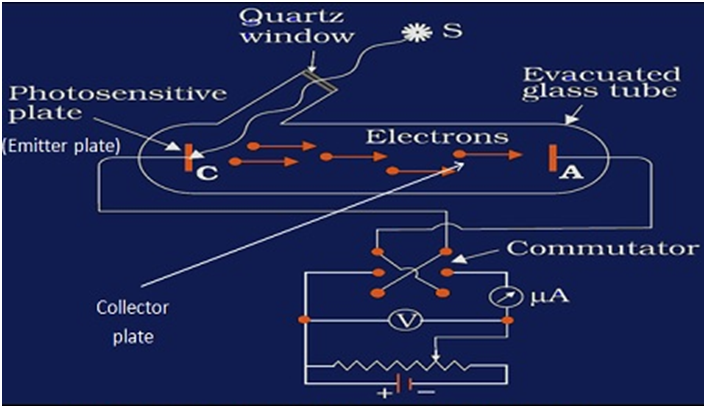
EXPERIMENTAL STUDY OF PHOTOELECTRIC EFFECT
- Evacuated tube consist of photosensitive plate (emitter) and the metal plate (collector), so that electrons could freely flow from emitter to collector without any air resistance
- Photosensitive plate (emitter) to absorb visible light and emit electrons
- Metal plate (collector) to receive electrons emitted from the emitter, thus constituting a photoelectric current flowfrom collector plate to the emitter plate (opposite to the flow of electrons)
- Monochromatic light of short wavelength (meaning high frequency)
- Battery to accelerate emitted electrons through a potential difference
- Voltmeter to measure the potential difference between the emitter and the collector plates due to photoelectric current flow
- Ammeter to measure the value of photoelectric current.
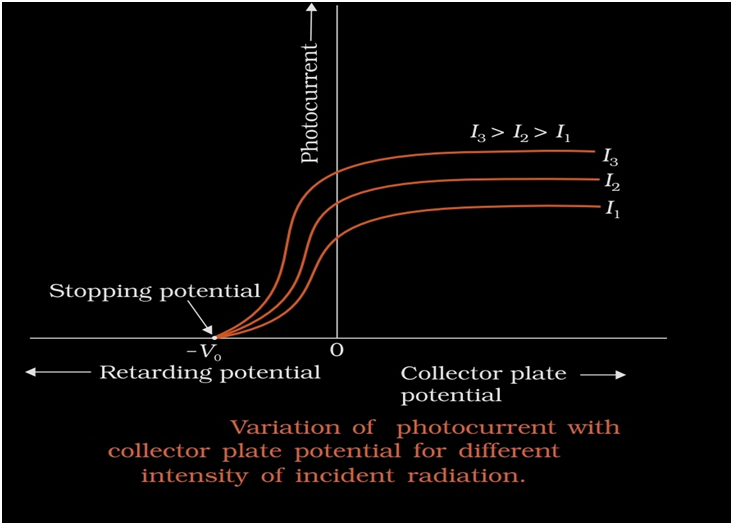
Effect of potential on photoelectric current
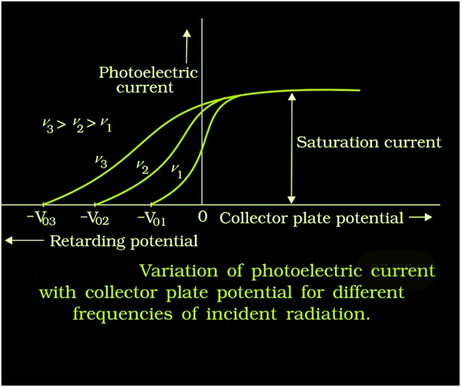
Effect of frequency of incident radiation on stopping
EINSTEIN’S PHOTOELECTRIC EQUATION: ENERGY QUANTUM OF RADIATION
Einstein resolved this problem using Planck’s revolutionary idea that light was a particle. The energy carried by each particle of light (called quanta or photon) is dependent on the light’s frequency (ν) as shown:
E = hν
Where h = Planck’s constant = 6.6261 × 10⁻³⁴ J.
A part of this energy is used to remove the electron from the metal atom’s grasp and the rest is given to the ejected electron as kinetic energy. Electrons emitted from underneath the metal surface lose some kinetic energy during the collision. But the surface electrons carry all the kinetic energy imparted by the photon and have the maximum kinetic energy.
mathematically :
Energy of photon = energy required to eject an electron (work function) + Maximum kinetic energy of the electron
E = W + KE
Hv = W + KE
KE = hv – w
The energy of a photon with this frequency must be the work function of the metal.
W = hv0
The, Maximum kinetic energy equation,
KE = 1/2mv2max=hv–hv0
1/2mv2max=h(v−v0)
Vmax is the maximum kinetic energy of the electron. It is calculated experimentally using the stopping potential. Please read our article on Lenard’s observations to understand this part.
ev0 = 1/2mv2max
1. Atomic Spectra
- Books Name
- Physics Book Part l and ll
- Publication
- Grow Career Publication
- Course
- CBSE Class 12
- Subject
- Physics
Chapter 12: ATOMS

Atomic Spectra
ALPHA-PARTICLE SCATTERING AND RUTHERFORD’S NUCLEAR MODEL OF ATOM
Rutherford proposed a new model of the atom based on Alpha-Particle Scattering experiment.In 1911, Ernst Rutherford suggested some experiments to H. Geiger and E. Marsden. Both scientists performed an experiment whose schematic diagram is shown in the figure given. Alpha-Particle scattering and Rutherford’s Nuclear Model of Atom They directed a beam of 5.5 MeV α-particles emitted from a radioactive source at a thin metal foil made of gold. The beam was allowed to fall on a thin foil of gold thickness 2.1 × 10⁻⁷ m.
The scattered alpha-particles were observed through a rotatable detector consisting of zinc sulphide screen and a microscope. The scattered alpha-particles on striking the screen produced brief light flashes or scintillations. These flashes may be viewed through a microscope and the distribution of the number of scattered particles may be studied as a function of angle of scattering
Observation of the Alpha (α) scattering Experiment
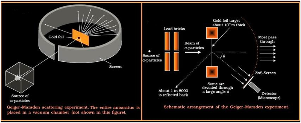
Many of the α-particle pass through the foil which means that they do not suffer any collisions. Approximately 0.14% of the incidents α-particles scatter by more than 10 and about 1 in 8000 deflect by more than 900.
- Scattering of alpha particle is due to columbic force between positive charge of α particle and positive charge of atom.
- Rutherford’s experiments suggested the size of the nucleus to be about 10–15 m to 10–14 m.
- The electrons are present at a distance of about 10,000 to 100,000 times the size of the nucleus itself.
- Atom has a lot of empty space and the entire mass of the atom is confined to very small central core also known as nucleus.
ATOMIC SPECTRA
Atoms have an equal number of negative and positive charges. Atoms were described as a spherical cloud of positive charges with embedded electrons in Thomson’s concept. In Rutherford’s model, one tiny nucleus carries the majority of the atom’s mass, as well as its positive charges, and the electrons orbit it.
The study of the electromagnetic radiation received or emitted by atoms is known as atomic spectroscopy. There are three different forms of atomic spectroscopy:
The transfer of energy from the ground state to an excited state is the subject of atomic emission spectroscopy. Atomic emission can explain the electronic transition.
Atomic absorption spectroscopy: For absorption to occur, the lower and higher energy levels must have equivalent energy differences. The notion that free electrons created in an atomizer can absorb radiation at a given frequency is used in the atomic absorption spectroscopy principle. The absorption of ground-state atoms in the gaseous state is measured.
Atomic fluorescence spectroscopy combines atomic emission and atomic absorption since it uses both excitation and de-excitation radiation.
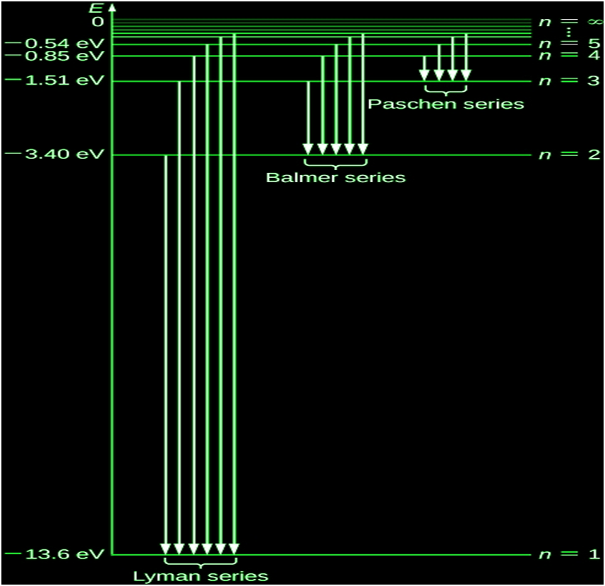
THE LINE SPECTRA OF THE HYDROGEN ATOM
A hydrogen atom is made up of several line spectrum series, including:
1.Pfund Series
2.Brackett Series
3.Paschen Series
4.Balmer Series
5.Lyman Series
RIES:
- Balmer Series:
First scientist to discover a spectral series of hydrogen atom
It consist of visible radiation spectrum
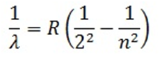
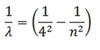
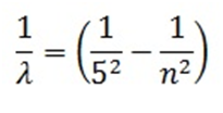
Experimentally, he found that these spectral lines could be expressed mathematically in the form of wavelength as:
![]()
Here R= Rhydberg constant = 109677cm-1(found experimentally), n= 3, 4, 5…… (higher discrete energy state from which electron jumps to 2nd energy state thus emitting radiation)
λ = wavelength of emitted radiation in (cm)
For maximum wavelength(λmax) in the Balmer series, n=3 (has to be minimum):

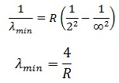
For minimum wavelength (λmin) in the Balmer series, n=∞(has to be minimum):
- Lyman Series:
Spectral series when radiation emitted is due to jumping of electron from higher energy states to ground state
Mathematically expressed as
Here n= 2, 3, 4…
For maximum wavelength in the Lyman series, n=2 (has to be minimum):
λmax = 4/3R
For minimum wavelength in the Lyman series, n=∞(has to be minimum):
λmin = 1/R
Similarly, all other series could be expressed as:
- Paschen Series:
Mathematically expressed as
![]()
Here n= 4, 5, 6…
- Bracket Series:
Mathematically expressed as
Here n= 5, 6, 7…
- PfundSeries:
Mathematically expressed as
Here n= 6, 7, 8…
THE LINE SPECTRA OF THE HYDROGEN ATOM
Bohr’s model of the hydrogen atom is the very first model of atomic structure that correctly explained the radiation spectra of atomic hydrogen. The model has a special place in the history of physics because it introduced an early quantum theory, which brought about new developments in scientific thought and later culminated in the development of quantum mechanics. To understand the specifics of Bohr’s model, we must first review the nineteenth-century discoveries that prompted its formulation.


![]()
An empirical formula to describe the positions (wavelengths) lambda of the hydrogen emission lines in this series was discovered in 1885 by Johann Balmer. It is known as the Balmer formula
The constant is called the Rydberg constant for hydrogen. In (Figure), the positive integer n takes on values n=3,4,5,6 for the four visible lines in this series. The series of emission lines given by the Balmer formula is called the Balmer series for hydrogen. Other emission lines of hydrogen that were discovered in the twentieth century are described by the Rydberg formula, which summarizes all of the experimental data
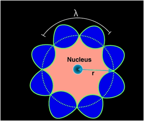
DE BROGLIE’S EXPLANATION OF BOHR’S SECOND POSTULATE OF QUANTISATION

The particle waves can be viewed analogously to the waves travelling on a string. Particle waves can lead to standing waves held under resonant conditions. When a stationary string is plucked, a number of wavelengths are excited. On the other hand, we know that only those wavelengths survive which form a standing wave in the string, that is, which have nodes at the ends.
2πrk = kλ
Let this be equation (1).
Λ = h/p
P is electron’s momentum
H = Planck’s constant
Λ = h/mvk
Let this be equation (2).
Where mvk is the momentum of an electron revolving in the kth orbit. Inserting the value of λ from equation (2) in equation (1) we get,
2πrk = kh/mvk
Mvkrk = kh/2π
1. Atomic Masses and Composition of Nucleus
- Books Name
- Physics Book Part l and ll
- Publication
- Grow Career Publication
- Course
- CBSE Class 12
- Subject
- Physics
Chapter 13: Nuclei

Atomic Masses and Composition of Nucleus
Nucleus of an Atom – atomic mass
An atom is tiny and therefore its mass is also proportionally minute. A regular unit of mass such as a Kilogram (Kg) cannot be used to weigh something as small as an atom and to address this issue, scientists have created a new unit of mass. It is called the Atomic Mass Unit (u).
1 u = one atom of C-12/ 12 = 1.992647 10-26/ 12 kg
1 u = 1.660539 10-27 kg
Nucleus of an Atom – Composition
The Nucleus of an atom consists of a tightly packed arrangement of protons and neutrons. These are the two heavy particles in an atom and hence 99.9% of the mass is concentrated in the nucleus.
SIZE OF THE NUCLEUS
- The alpha particles got deflected because of repulsion with the nucleus as alpha particles are positively charged.They get repelled because they are both positively charged.
- Very small number of alpha particles got deflected proving that nucleus is very small in size.
- It was found that the radius of a nucleus (R) of mass number A is given as :-
- R=R0A1/3 where A = mass number and R0=constant.
- Volume of a nucleus is ∝to the mass number.
- V =(4/3)πR3 , Also R ∝(A)1/3
- R3∝A
- Therefore, V ∝ R3∝
- Density of nucleus is independent of mass number.
Mass – Energy
Einstein showed from his theory of special relativity that it is necessary to treat mass as another form of energy. Before the advent of this theory of special relativity it was presumed that mass and energy were conserved separately in a reaction. Einstein gave the famous mass-energy equivalence relation
E = mc2
Nuclear binding energy
Importance of nuclear binding energy describes how strongly nucleons are bound to each other. By determining its value we will come to know whether the neutrons and protons are tightly or loosely bound to each other.

If nuclear binding energy is high -> high amount of energy is needed to separate the nucleons this means nucleus is very stable.
Energy required holding neutrons and protons together therefore keeps the nucleus intact.
It can also be defined as the energy needed to separate the nucleons from each other.
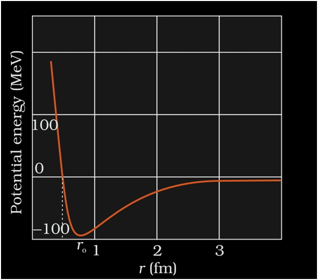
NUCLEAR FORCE
- It is the strong attractive force that binds the nucleons together.
- When the nuclear force is compared to other forces of nature like gravitational or coulomb’s force etc.it is the strongest of all the forces.
- As protons are positively charged they repel each other.This force of repulsion is given by Coulomb’s force of repulsion.
- This nuclear force is stronger than the coulomb’s force so it overcomes the force of repulsion.
- This is the reason neutrons and protons are held together inside the nucleus.
- The force with which the nucleons are bound together is known as nuclear force.
Radioactivity
Nuclear instability, an atom’s nucleus exhibits the phenomenon of Radioactivity. Energy is lost due to radiation that is emitted out of the unstable nucleus of an atom. Two forces, namely the force of repulsion that is electrostatic and the powerful forces of attraction of the nucleus keep the nucleus together.
- Gamma Decay (Photons having high energy are emitted)
- Beta Decay (Emission consists of Electrons)
- Alpha Decay (Emission consists of Helium nucleus)
Alpha decay
In alpha decay α particles are emitted.Daughter nucleus is formed from the parent nucleus.
The atomic number decreases by 2 and Mass number increases by 4.
It is a very spontaneous process and happens on its own.
It occurs only in radionuclides.
For example:-
23892U (unstable) --> 90234Th + 24He
(Uranium (U) is known as parent nucleus and Thorium (Th) is known as daughter nucleus).
24He is α particle.
General form of alpha decay: -AZX (parent) à(A-4) (Z-2) Y + 24He
Where Y is daughter nucleus.
Q-value of alpha decay
Q-value is a parameter or a characteristic of a nuclear reaction which describes whether the reaction can take place or not.
Q-value is defined as difference in the initial mass energy and final mass energy of decayed products.
Consider the general equation:-
AZX (parent) -->(A-4) (Z-2) Y + 24
Initial rest mass energy Ui =[m (AZX) - Zme]c2
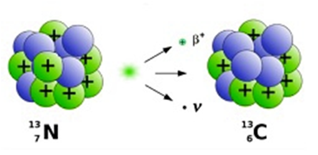
Beta decay
In case of beta decay either electron or positron is emitted.
Mass number remains the same.
β−decay --> Electron is emitted.
Atomic number increases by 1.
For example:- 3215P à1632S + e- + ̅ν where ̅ν =anti-neutrino
Q-value for β−decay:-
AZXàA (Z+1) Y + e-+ ̅ν
Initial rest mass energy Ui = [m (AZX) - Zme]c2
Gamma decay
In Gamma decay γ rays are emitted.γ rays are electromagnetic waves with short wavelength. Most of the daughter nuclei of alpha decay and beta decay are in excited state. As a result they are unstable.When the daughter nuclides try to transit from excited state to ground state they emit radiations.
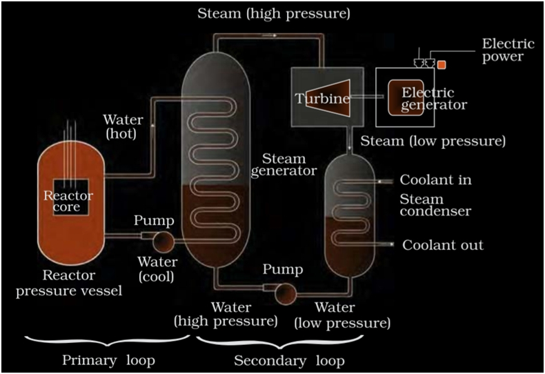
- Nuclear Energy
Electric energy can be harnessed from nuclear energy. Nuclear energy is the energy that holds together the nuclei of atoms. Nuclear energy is obtained from nucleusby either Breaking of heavy nucleus into 2 relatively lighter nuclei known as nuclear fission or by Combining 2 lighter nuclei to form a heavy nucleus known as nuclear fusion.
1.Intrinsic Semiconductor
- Books Name
- Physics Book Part l and ll
- Publication
- Grow Career Publication
- Course
- CBSE Class 12
- Subject
- Physics
Chapter 14: Semiconductors Electronics
Intrinsic Semiconductor
CLASSIFICATION OF METALS, CONDUCTORS AND SEMICONDUCTORS
Metals:
They possess very low resistivity (or high conductivity).
![]()
Semiconductors:
They have resistivity or conductivity intermediate to metals and insulators.
![]()
Insulators:
They have high resistivity (or low conductivity).
![]()
The values of ρ and σ have given above are indicative of the magnitude and could well go outside the ranges as well.
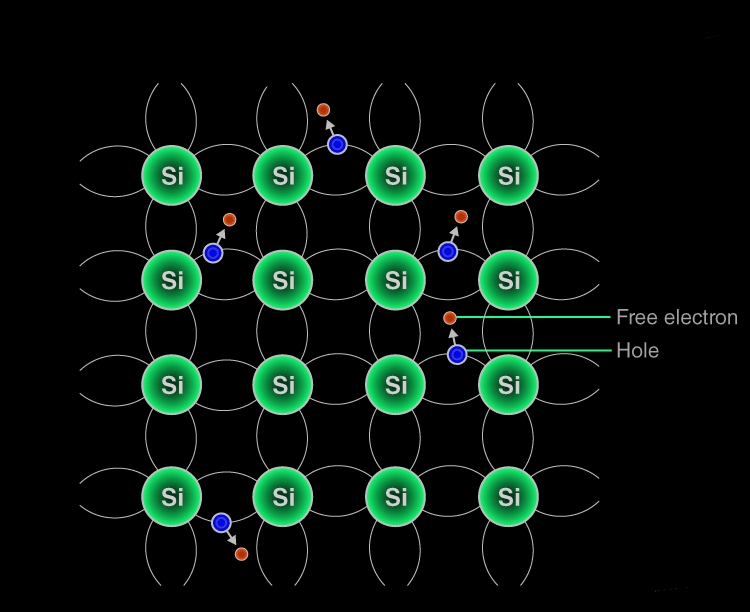
Intrinsic Semiconductors
Semiconductors that are chemically pure, in other words, free from impurities are termed as intrinsic semiconductors. The number of holes and electrons is therefore determined by the properties of the material itself instead of the impurities. In intrinsic semiconductors, the number of excited electrons is equal to the number of holes; n = p.
Working Mechanism of Intrinsic Semiconductors
Electronic Configuration of Silicon and Germanium
Silicon 1s2 2s22p6 3s2 3p2
Germanium 1s2 2s2 2p6 3s2 3p6 4s2 3d10 4p2
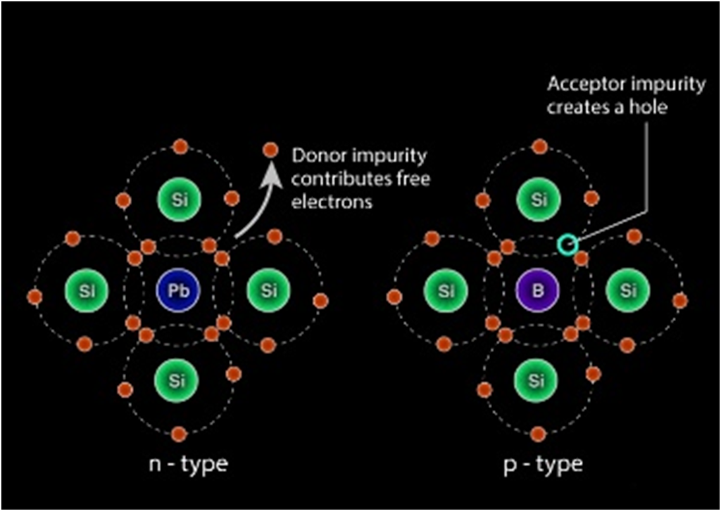
EXTRINSIC SEMICONDUCTOR
n-type semiconductors
When a tetravalent atom such as Si or Ge is doped with a pentavalent atom, it occupies the position of an atom in the crystal lattice of the Si atom. The four of the electrons of the pentavalent atom bonds with the four neighboring silicon atoms and the fifth one remains weakly bound to the parent atom. As a result of this, the ionization energy required to set the fifth electron free is very less and the electrons become free to move in the lattice of the semiconductor. Such semiconductors are termed as n-type semiconductors.
1. Elements of a Communication System
- Books Name
- Physics Book Part l and ll
- Publication
- Grow Career Publication
- Course
- CBSE Class 12
- Subject
- Physics
Chapter 15: Communication System

Elements of a Communication System
Communication Systems
The communication system is a system which describes the information exchange between two points. The process of transmission and reception of information is called communication.
Types Of Communication Systems
Depending on Signal specification or technology, the communication system is classified as follows
- Analog
Analog technology communicates data as electronic signals of varying frequency or amplitude. Broadcast and telephone transmission are common examples of Analog technology.
- Digital
In digital technology, the data are generated and processed in two states: High (represented as 1) and Low (represented as 0). Digital technology stores and transmits data in the form of 1s and 0s.
BASIC TERMINOLOGY USED IN ELECTRONIC COMMUNICATION SYSTEMS
The definitions of the terms used in the communication system are discussed below.
Information
Message or information is the entity that is to be transmitted. It can be in the form of audio, video, temperature, picture, pressure, etc.
Signal
The single-valued function of time that carries the information. The information is converted into an electrical form for transmission.
Transducer
A device or an arrangement that converts one form of energy to the other. Example: Microphone – converts audio signals into electrical signals. Photodetector – converts light signals into electrical signals.
Amplifier
The electronic circuit or device that increases the amplitude or the strength of the transmitted signal is called an amplifier.
Modulator
As the original message signal cannot be transmitted over a large distance because of their low frequency and amplitude, they are superimposed with high frequency and amplitude wave called carrier wave.
Transmitter
It is the arrangement that processes the message signal into a suitable form for transmission and subsequently reception.
Channel
A channel refers to a physical medium such as wire, cables, space through which the signal is passed from the transmitter to the receiver.
Noise
Noise is one of the channel imperfection or impairment in the received signal at the destination. There are external and internal sources that cause noise.
BANDWIDTH OF SIGNALS
Bandwidth refers to the frequency range over which an equipment operates or the portion of the spectrum occupied by the signal. Different types of signals (music, picture or computer data) require different bandwidth.
- Speech signal requires a bandwidth of 2800 Hz (3100 Hz – 300 Hz) for telephonic conversation.
- Video signals for transmission of pictures require about 4.2 MHz of bandwidth.
- A TV signal contains both voice and picture and is usually allocated 6 MHz of bandwidth for transmission.
Bandwidth of Transmission Medium
Different types of transmission media offer different bandwidths.
- The commonly used transmission media are wire, free space and fiber optic cable.
- Coaxial cable offers a bandwidth of approximately 750 MHz. Such cables are normally operated below 18 GHz.
2. Photon
- Books Name
- Physics Book Part l and ll
- Publication
- Grow Career Publication
- Course
- CBSE Class 12
- Subject
- Physics
PARTICLE NATURE OF LIGHT: THE PHOTON
Photoelectric effect thus gave evidence to the strange fact that light in
interaction with matter behaved as if it was made of quanta or packets of
energy, each of energy hv.
Is the light quantum of energy to be associated with a particle? Einstein
arrived at the important result, that the light quantum can also be
associated with momentum (hv/c ). A definite value of energy as well as
momentum is a strong sign that the light quantum can be associated
with a particle. This particle was later named photon.
Wave Nature of Matter
The wave nature of matter is one of the most counter-intuitive concepts in Physics. You have seen examples of both particle nature of light and wave nature of light. You know about the Photoelectric effect due to Albert Einstein’s courtesy. In the photoelectric effect, the electrons and photons exhibit the properties of a particle, just like a billiard ball.
De Broglie’s Equation
Light and radiation are both particles and waves, according to De Broglie’s hypothesis, thus matter must also have a particle and wave character. Wave theory was born as a result of the de Broglie connection.
De Broglie’s equation is given as:
Λ = h ⁄ p = h ⁄ (mv)
Where,
Λ is the wavelength of particle,
P is the momentum of a particle,
H is the Planck’s constant,
M is the mass of particle, &
V is the velocity of the particle.
De Broglie’s Hypothesis
The momentum of a photon having energy E is given as:
P = E ⁄ c
The speed of light in a vacuum is represented by the letter c.≥
Planck’s idea states that the energy of a photon is determined by its frequency and wavelength.
E = h v = h c ⁄ λ
The energy should be equal, implying:
H c ⁄ λ = p c
Λ = h ⁄ p
De Broglie concluded that the aforementioned relationship should apply to particles as well. P=mv is the momentum of a particle with mass m moving at a speed of v. As a result, it must have a wavelength of
Λ = h ⁄ p = h ⁄ (mv)
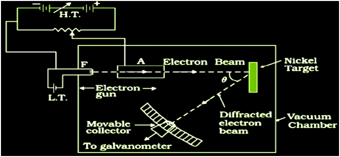
DAVISSON AND GERMER EXPERIMENT
The experiment is performed by varying the accelerating voltage from 44 V to 68 V. A strong peak observed in the intensity (I) of the scattered electron for an accelerating voltage of 54 V at a scattering angle 50º. The appearance of the peak in a particular direction is due to the constructive interference of electrons scattered from different layers of the regularly spaced atoms of the crystals. From the electron diffraction theory, the wavelength of matter waves producing maxima at 50º is calculated to be λ= 0.165 nm.
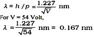
Thus, there is an excellent agreement between the theoretical value and the experimentally obtained value of de Broglie wavelength. Davisson- Germer experiment thus strikingly confirms the wave nature of electrons, particles in general and the de Broglie relation.
2. p-n Junction and diode
- Books Name
- Physics Book Part l and ll
- Publication
- Grow Career Publication
- Course
- CBSE Class 12
- Subject
- Physics
P-n Junction and diode
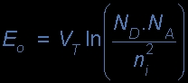
p-n JUNCTION
The total charge on each side of a PN Junction must be equal and opposite to maintain a neutral charge condition around the junction. If the depletion layer region has a distance D, it therefore must therefore penetrate into the silicon by a distance of Dp for the positive side, and a distance of Dn for the negative side giving a relationship between the two of:
Dp*NA = Dn*ND
in order to maintain charge neutrality also called equilibrium.
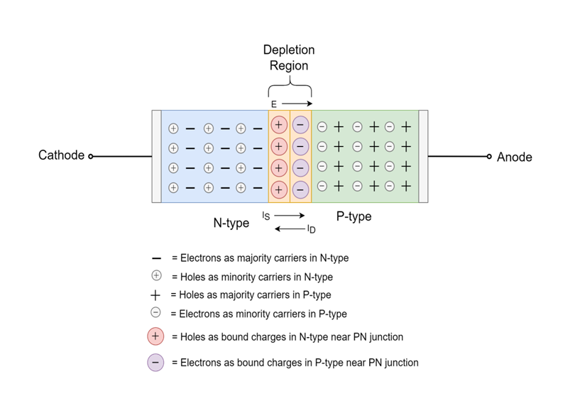
SEMICONDUCTOR DIODE
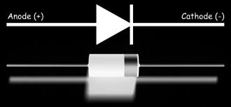
A Semiconductor Diode is a p-n junction that has metallic contacts at both of its ends in order to apply external voltage. It is a p-n junction diode. It has the ability to conduct current in only one direction.
p-n junction diode under forward bias
When an external voltage V is applied across a semiconductor diode such That p-side is connected to the positive terminal of the battery and n-side To the negative terminal.
p-n junction diode under reverse bias
When an external voltage (V ) is applied across the diode such That n-side is positive and p-side is negative, it is said to be Reverse biased.
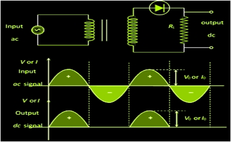
APPLICATION OF JUNCTION DIODE AS A RECTIFIER
In a half-wave rectifier, one half of each a.c input cycle is rectified. When the p-n junction diode is forward biased, it gives little resistance and when it is reversing biased it provides high resistance. During one-half cycles, the diode is forward biased when the input voltage is applied and in the opposite half cycle, it is reverse biased. In the Full-wave rectifier circuits are used for producing an output voltage or output current which is purely DC. The main advantage of a full-wave rectifier over half-wave rectifier is that such as the average output voltage is higher in full-wave rectifier, there is less ripple produced in full-wave rectifier
SPECIAL PURPOSE p-n JUNCTION DIODES
Zener diode
It is a special purpose diode, named after the inventor C. Zener It is designed to operate under reverse bias in the breakdown region

The symbol for Zener diode is
Fabrication – It has heavily doped p- side and n-side. Due to this, the depletion region formed is very thin about < 10-6. . Hence, the field at the junction is extremely high about -5 * 106 V/m for a small reverse bias voltage of 5 Volts
Light emitting diode
It is a heavily doped p-n junction which under forward bias emits Spontaneous radiation. The diode is encapsulated with a ttransparen Cover so that emitted light can come out.The V-I characteristics of a LED is similar to that of a Si junction Diode. But the threshold voltages are much higher and slightly different For each colour. The reverse breakdown voltages of LEDs are very low, Typically around 5V. So care should be taken that high reverse voltages Do not appear across them.
Solar cell
A solar cell is basically a p-n junction which Generates emf when solar radiation falls on the p-n junction. It works on the same principle (photovoltaic effect) as the photodiode, except that No external bias is applied and the junction area Is kept much larger for solar radiation to be Incident because we are interested in more power.
JUNCTION TRANSISTOR
n-p-n transistor: Here two segments of n-type semiconductor (emitter and collector) are separated by a segment of p-type Semiconductor (base).
P-n-p transistor: Here two segments of p-type semiconductor (termed as emitter and collector) are separated by a segment of n-type semiconductor (termed as base).
The schematic representations of an n-p-n and a p-n-p Configuration.
DIGITAL ELECTRONICS AND LOGIC GATES
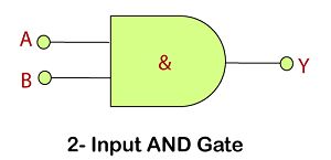
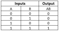
AND Gate
This gate works in the same way as the logical operator "AND". The AND gate is a circuit that performs the AND operation of the inputs. This gate has a minimum of 2 input values and an
Logic Design
Truth Table
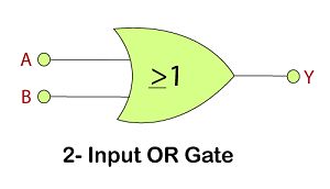
OR Gate
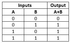
This gate works in the same way as the logical operator "OR". The OR gate is a circuit which performs the OR operation of the inputs.
Logic Design
Truth Table
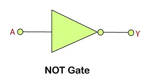
NOT Gate
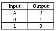
The NOT gate is also called an inverter. This gate gives the inverse value of the input value as a result.
Logic Design
Truth Table
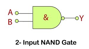
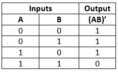
NAND Gate
The NAND gate is the combination of AND gate and NOT gate. This gate gives the same result as a NOT-AND operation.
Logic Design
Truth Table
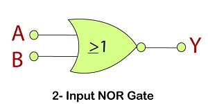
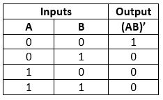
NOR Gate
The NOR gate is the combination of an OR gate and NOT gate. This gate gives the same result as the NOT-OR operation.
Logic Design
Truth Table
INTEGRATED CIRCUITS
(i) The concept of fabricating an entire circuit on a small single chip of semiconductor is called Integrated circuit; The chip dimensions are as small as 1mm * 1 mm or even less than that
(ii) The integrated chip can be categorised into (a) linear or analog IC (b) digital IC
(iii) Linear or Analog IC – The signals change continuously over a range of values between maximum and minimum; The output varies linearly as the input ; The most useful linear IC is an operational amplifier
(iv) DigitaIC – These have two values – high and low; These contain logical gates. – Depending upon the number of circuit components or logic gates used, they can be classified into SSI, MSI, LSI or VLSI
2. Electromagnetic Waves
- Books Name
- Physics Book Part l and ll
- Publication
- Grow Career Publication
- Course
- CBSE Class 12
- Subject
- Physics
Electromagnetic Waves
Propagation of Electromagnetic Waves
Various propagation modes for em waves are shown in the figure given below
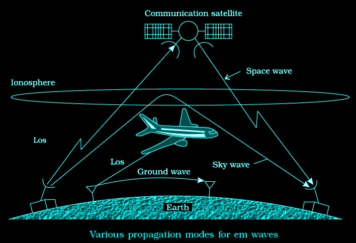
Ground wave propagation
Radio waves traveling through atmosphere and moving along the surface of the earth are termed as ground waves. Ground wave propagation is suitable for low frequencies (500 kHz to 1500kHz) or for radio broadcast at long wavelength i.e., upto 1 MHz.
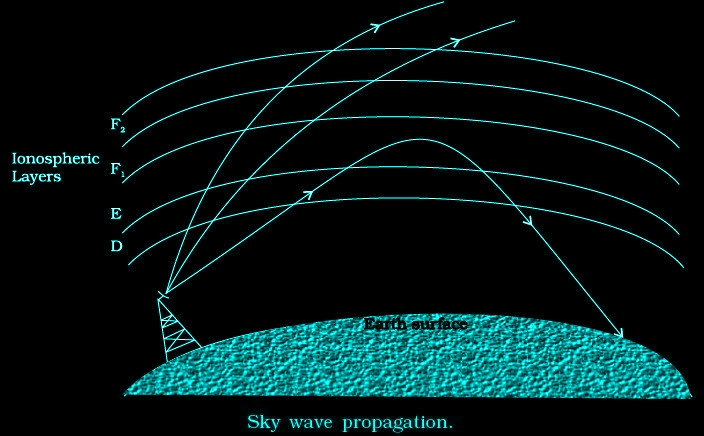
Sky wave propagation
The frequency range from a few MHz up to 30 to 40 MHz, long distance communication can be achieved by ionospheric reflection.
MODULATION AND ITS NECESSITY
Transmission of information by communication systems over large distances is quite a feat of human ingenuity. We can talk, video chat and text anyone on this planet! The communication system uses a very clever technique called Modulation .
Types of Modulation
1.Amplitude Modulation
2.Frequency Modulation
3.Phase Modulation
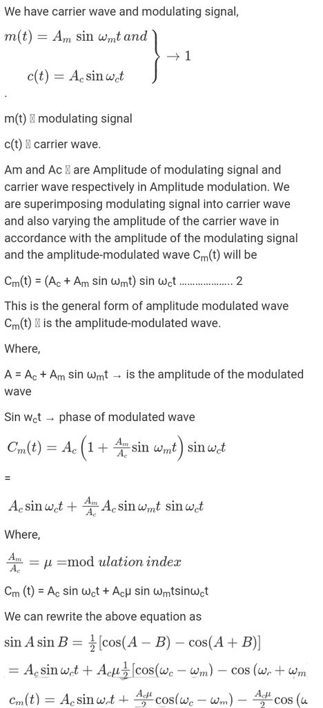
AMPLITUDE MODULATION
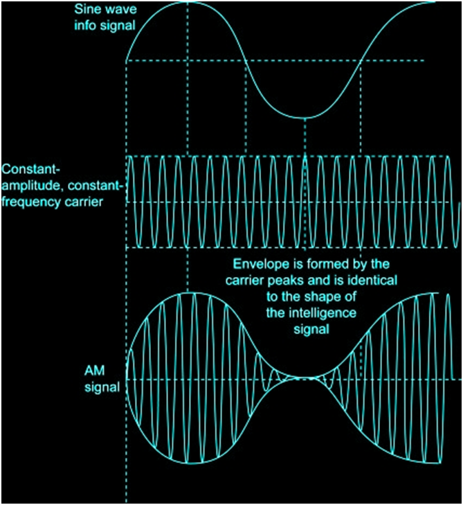
In AM, the voltage or power level of the information signal changes the amplitude of the carrier in proportion. With no modulation, the AM carrier is transmitted by itself.
PRODUCTION OF AMPLITUDE MODULATED WAVE
DETECTION OF AMPLITUDE MODULATED WAVE
The transmitted message gets attenuated in propagating through the Channel. The receiving antenna is therefore to be followed by an amplifier And a detector. In addition, to facilitate further processing, the carrier Frequency is usually changed to a lower frequency by what is called an
Intermediate frequency (IF) stage preceding the detection.