 Grow Career Publication
 Madhava Publications
1.Magnetic Force
- Books Name
- Physics by Anshu Physics Book
- Publication
- Madhava Publications
- Course
- CBSE Class 12
- Subject
- Physics
INTRODUCTION

Concepts of both electricity and magnetism was known for almost 2000 years. These two phenomena were considered as independent phenomena. But in 1820 a Danish physicist noticed that a current-carrying wire caused a noticeable deflection in the magnetic compass needle placed near that current-carrying wire. So he concluded that moving charges or currents produces magnetic fields.
Later another scientist Oersted did some experiments with a magnet and a coil and found that the motion of the magnet near the coil is producing current in the coil. Later Faraday made laws of electromagnetic Induction based on the Oersted experiment’s observation. He concluded that change in a magnetic field produces current.
In 1864, the laws obeyed by electricity and magnetism were unified and formulated. James Maxwell then realized that light is an electromagnetic wave. After the unification of electricity, magnetism and electromagnetic waves as a single unit called electrodynamics, remarkable scientific and technological progress took place in the 20th century.
What will we learn in this chapter?
In this chapter, we will study magnetostatics. It is a phenomenon associated with steady currents. When a steady current flows through a wire, it produces a constant magnetic field around it. We shall see how particles can be accelerated to very high energies in a cyclotron.
We will see how currents and voltages are detected by a galvanometer.
Magnetic force
Let’s first recapitulate whatever we have learned so far. First, we studied about the static property of the charges in “Electrostatics”, we understood how charges exert force on each other, we discussed electric fields, electric flux, and electric potentials. Then in the later chapter “ current electricity’’ we studied the phenomena related to charges in motion. We have discussed currents, mobility, drift velocity, resistivity and many more.
- Magnetic forces: Sources and fields
In this unit, we will study another property of moving charges.
Moving charges produce magnetic fields around, this property is called the magnetic effect of current.
- Also when a current carrying wire is placed in a magnetic field, it will experience some magnetic force on it.
- Just like static charges produce an electric field, moving charges produce magnetic fields. Magnetic field is again a vector field.
- The basic property of a magnetic field is very similar to an electrical field.
- Magnetic fields are also found to obey the principle of superposition.
- A charge particle moving in magnetic field also experience magnetic force
- Magnetic field and Lorentz force
Suppose we have a charge ‘q’ in an electric field ‘E’ so it will experience an electric force on it
Electric force
Now suppose we have switched on the magnetic field also and the charge is moving with a speed ‘v’ in this magnetic field ‘B’
So it will experience magnetic force on it.
Magnetic force
So total force on the charged particle when it moves in the electric and magnetic force is given by the following expression
The above force F is the total force on the charged particle and is called Lorentz force.
Features of magnetic force
- It depends on q, v and B. Magnetic force on a negative charge is opposite to magnetic force on a positive charge.
- It involves the cross-product of velocity and magnetic field. so if the velocity and magnetic field are parallel to each other, the magnetic force will be zero. magnetic force will be maximum when velocity is perpendicular to field B.
- If charge is at rest so V=0 then magnetic force will be zero. Only a moving charge feels magnetic force
- Magnetic force is a conservative force, It do not change the energy of the system
- Magnetic force only changes direction of motion of charges and does not change the speed of the charges. S.I unit of Magnetic force is Tesla.
- Magnetic force on current carrying conductor
We can extend our analysis for force due to the magnetic field on a single moving charge to a straight rod carrying current. Inside a current-carrying conductor, charges are moving inside the conductor and when this current-carrying conductor is placed in magnetic force, moving charge inside the conductor experience magnetic force as discussed above
Suppose we have ‘n’ no of charges per unit volume of the conductor of length ‘l’ and cross-section area ‘A’.
Here ‘vd’ = drift velocity of charges inside the conductor, q= e, a charge of carrier inside the conductor.
Now we know that current
So using 2 in 1 we get
The above formula is the formula for force on a current carrying conductor of length ‘L” and having current ‘I’ placed in magnetic field B.
Here
Motion in a magnetic field
Magnetic forces do not do any work on the charged particle or you can say that work done by magnetic forces on the charged particle moving in the magnetic field is zero.
You have learned in mechanics that
So if force and the displacement is perpendicular to each other then work done= 0
In the case of the magnetic motion of a charged particle in a magnetic field, The magnetic field and the velocity vector are always perpendicular to each other as shown. So no work is done.
Also from work-energy theorem, we have
So If the work done=0, then the change in kinetic energy of the charged particle would also be equal to zero. This means that the Kinetic energy of the charged particle moving in the magnetic field is constant. Also, the magnitude of the velocity of the charged particle moving in the magnetic field is constant. But the direction of velocity can be changed.
Motion of a charged particle in a Uniform Magnetic field
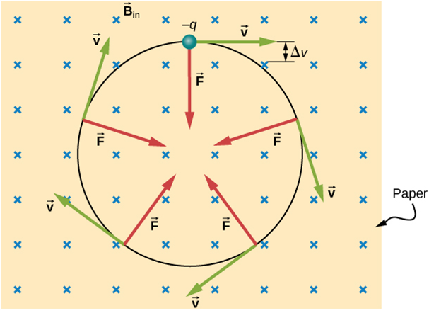
Case 1: Motion of charged particle is perpendicular to Magnetic field.
Suppose a charged particle of charge ‘q’ is moving with a speed ‘v ‘ perpendicular to the magnetic field. The magnetic force experienced by the charged particle would be.
This force will provide a centripetal force to the charged particle to move in a uniform circular motion.
centripetal force
So,
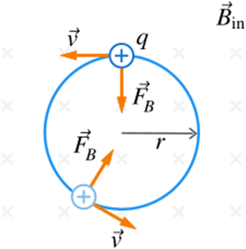
So we conclude that when a charged particle moves perpendicular to the magnetic field, the magnetic force on the charged particle acts like centripetal force and produces a circular motion perpendicular to the magnetic field.
The particle would describe a circle if ‘v’ and ‘B’ are perpendicular to each other.
Radius of circular path =
Time period of motion =
Frequency of the motion =
Case 2: Velocity is parallel to the magnetic field
Suppose we have a charged particle of charge ‘q’ moving with a velocity ‘v’ parallel to magnetic field B. The magnetic force on the charged particle will be
So we can conclude that when a charged particle moves parallel to the magnetic field then it will not experience any force on it and will continue its motion without any change in its motion.
Case 3: when the velocity vector makes an arbitrary angle with the magnetic field Suppose we have a charged particle with charge ‘q’ . It moves in magnetic field B with velocity ‘v’ making an angle ‘
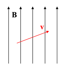
Since the velocity is in an arbitrary direction we can resolve the velocity in a direction parallel to B and perpendicular to B.
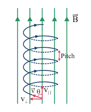
So we have two components of velocity: the perpendicular component will follow case 1 and the parallel component will follow case 2 described above.
Due to
So the resultant of the two motions will be helical motion.
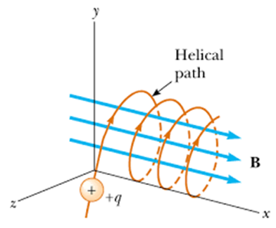
The radius of the helix is determined by
Time period
Motion in combined Electric and Magnetic field
When a charged particle of charge ‘q’ moves with velocity ‘v’ in the electric and magnetic fields, Lorentz force acts on it which is due to both electric and magnetic force.
F= Fe + Fm
For simplicity let's assume that the velocity, electric field and magnetic field are mutually perpendicular to each other.
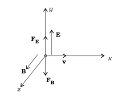
Here
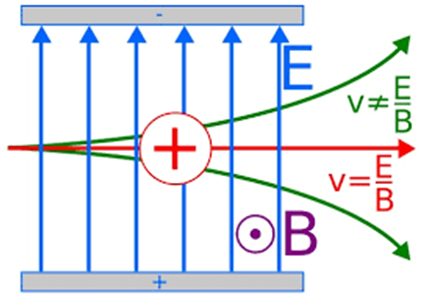
We can see that electric and magnetic forces are in opposite directions so if we adjust E and B such that magnitude of the two forces are equal. Then total force on the charge ‘q’ will be zero and the particle will go undeflected. This happens when
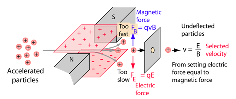
This condition can be used to select charged particles of particular velocity out of the beam containing charges with different speeds, therefore serving as a velocity filter.
Magnetic field due to the current element: Biot- Savart law
We know from the above discussion that the current carrying wire produces a magnetic field around it. This phenomenon is called the magnetic effect of current.
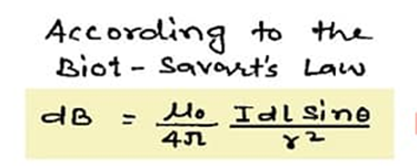
The relationship between current and magnetic field produced due to the current element is given by Biot-Savart Law.
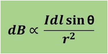
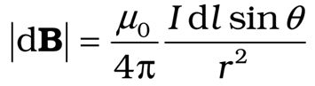
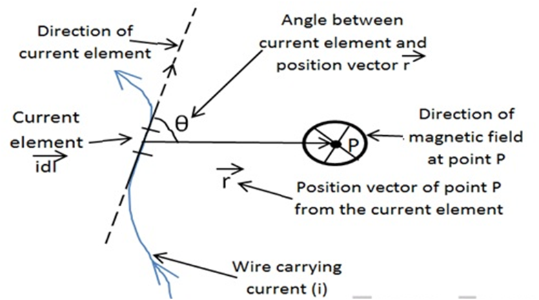
According to Biot-Savart law, the magnitude of magnetic field dB due to current element dl
- Is proportional to the length of the current element ‘dl’.
- Is proportional to the current in the wire.
- Is proportional to
- Is inversely proportional to the square of the distance between ‘r’ of the point P from the current element.
To remove the proportionality sign we need to put a constant.
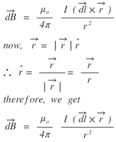
Vector form of Biot-Savart law.
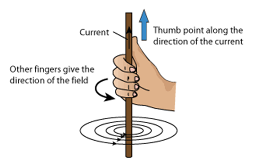
Direction of dB
Right-hand thumb rule: If we put our thumb of the right hand in the direction of the current, then the direction of the curl of our fingers will give the direction of the magnetic field.
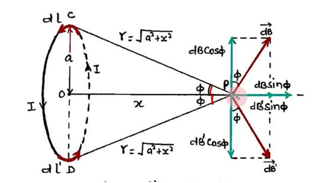
Magnetic field on the axis of the current carrying loop.
Suppose we have a current carrying loop, carrying current ‘I’ and radius R.
We need to find the magnetic at the axis of the coil at a distance ‘x’ from the center.
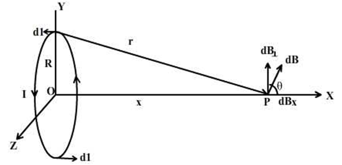
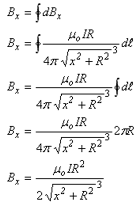
When we resolve dB along in the direction parallel to it and perpendicular to it, we will see that perpendicular components of dB due to half loop will be canceled by the other half of the current loop.
And parallel component of dB is integrated for the whole circular loop
Magnetic field due to current carrying loop using Biot-Savart law
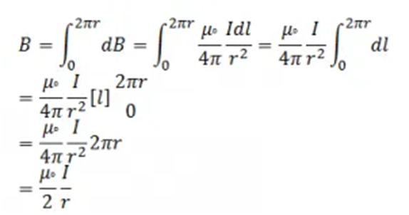
Suppose we have a currency-carrying loop of radius ‘r’ and carrying current ‘I’ and we have to find the magnetic field at the center of the circular loop at O.
From Biot-Savart law we have

Here
So to get B we have to integrate dB along the whole loop

2. Ampere's circuital law
- Books Name
- Physics by Anshu Physics Book
- Publication
- Madhava Publications
- Course
- CBSE Class 12
- Subject
- Physics
Introduction:
Like In Electrostatics we have coulomb's law to find electric fields due to charge distribution, but that is very tedious to use in many cases. So in case of some symmetry, we had Gauss's law that can be used to find electric fields in an easier way.
In the same manner in Magnetostatics we have the Biot-Savart law that can be used to find magnetic fields due to any current distribution.
But in the case of some symmetry we have, we can use ampere circuital law that can make our life easier.
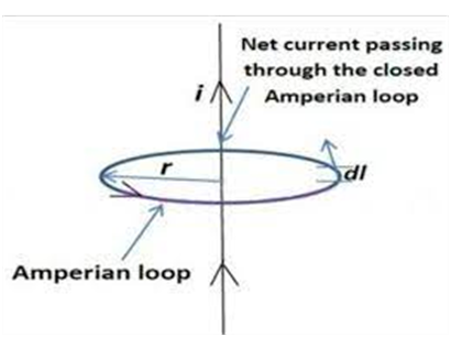
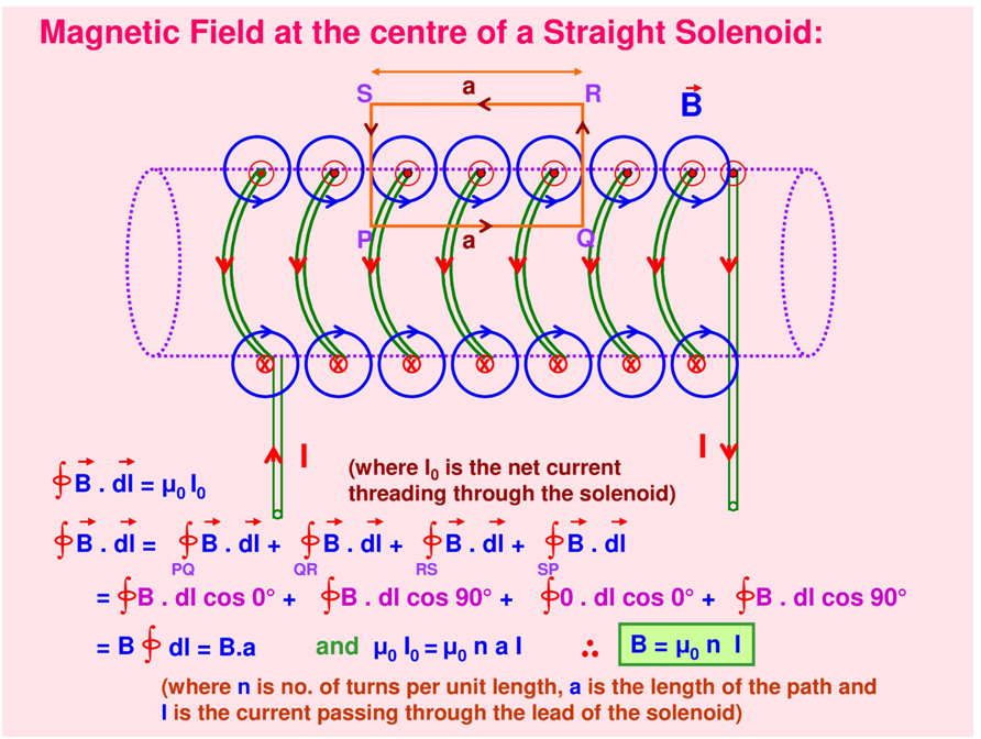
Ampere circuital law
Ampere circuital law states that the line integral of the magnetic field B around any closed circuit is equal to μ0 ( permeability constant) times the total current ‘
Mathematically,
Where
Ampere circuital law can be used to find magnetic field due to magnetic field in some symmetry case like long wire, circular loop, cylindrical conductor etc,
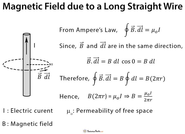
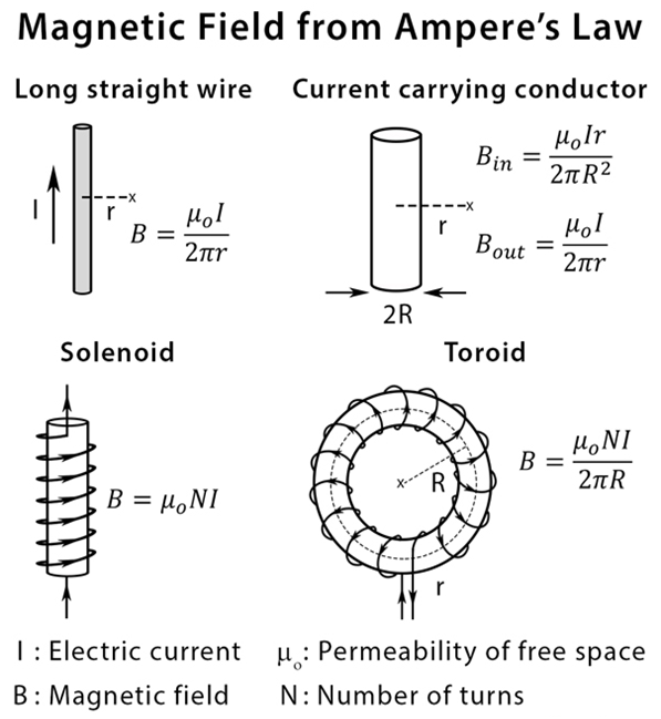
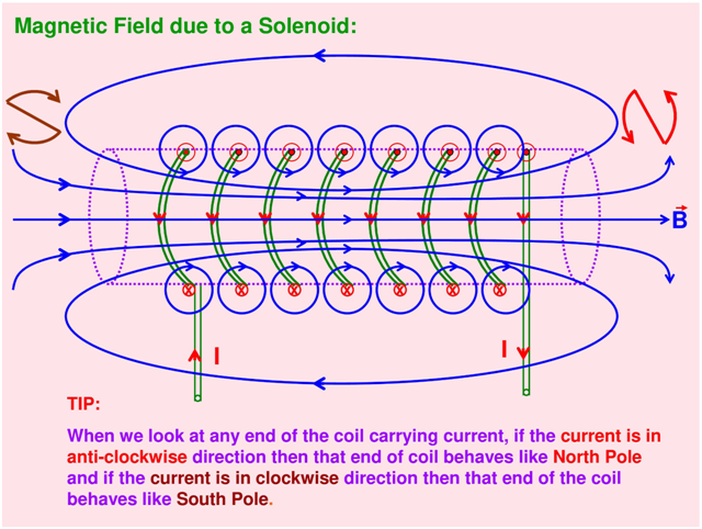
Above are some examples of magnetic fields in some standard cases. We will discuss Solenoid and toroid in detail
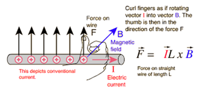
Force on a current carrying conductor in a magnetic field
When the conductor carrying current is placed in an external magnetic field, it experiences a mechanical force. The direction of the force is perpendicular to both the current and the magnetic field and it is given by Fleming’s right left-hand rule.
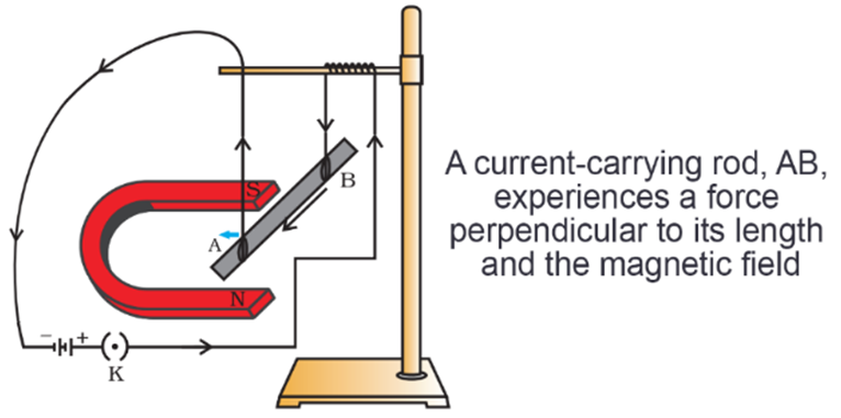
Cause of the force: A current is an assembly of moving charges and magnetic field exerts a force on moving charges, That is why a current-carrying conductor experiences a side-ways force as the force experienced by the moving charges( free electrons) is transmitted to the conductor as a whole.
The expression of the force will be derived as
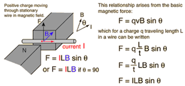
Thus Force on the current carrying conductor placed in a magnetic field is given by
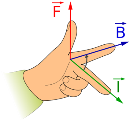
Direction of force is given by Fleming’s left-hand rule.
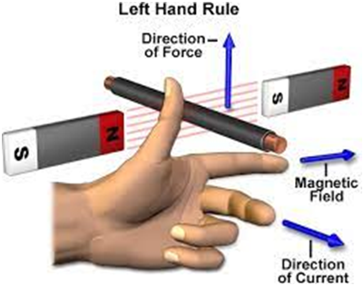
If we place the fingers of our left hand in mutually perpendicular directions. If the forefinger is along the direction of the magnetic field and the middle finger points in the direction of current then the thumb will give the direction of the force on the conductor.
The force between two parallel current
As we know, the current carrying conductor produces a magnetic field around it and when any current carrying conductor is placed in a magnetic field it will experience a force on it.
So if we have one current carrying conductor it will produce a magnetic field around it. If we place another current carrying conductor near the first conductor, it will actually be a current carrying conductor placed in the magnetic field and hence will experience a force on it.
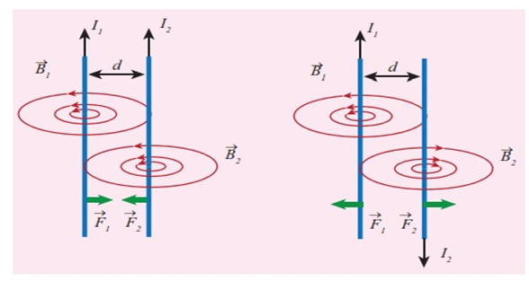
In the figure given above It is shown that two parallel current carrying conductors placed near each other exert force on each other.
- When they have parallel currents, they attract each other.
- When they have antiparallel current, they repel each other.
- The magnitudes of forces F1 and F2 are equal but they are in opposite directions which is in accordance with Newton’s third law.
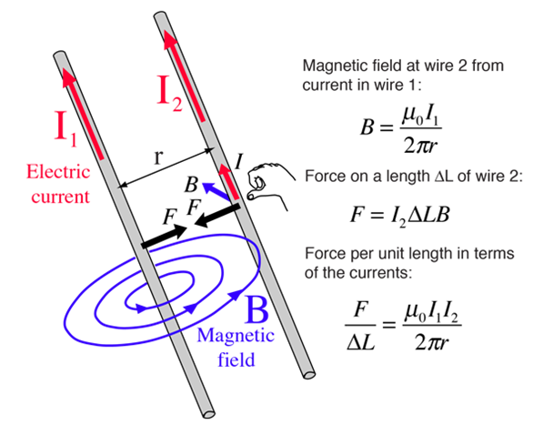
The force between two parallel current carrying conductors.
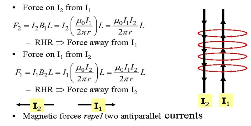
Consider two conductors having parallel currents
Force on 2nd conductor having length ‘L’ due to 1st conductor= F21
Force on 1st conductor due to 2nd conductor = F12
Force per unit length on each conductor
Similarly, force on two parallel conductors having antiparallel currents is shown below. Conductors having ant parallel currents repel each other.
Force on two straight wires having ant parallel currents.
Torque on a current loop in a uniform magnetic field.
The figure shows a rectangular loop carrying a steady current I and placed in the uniform magnetic field B. In this discussion, we will see that the current loop placed in uniform magnetic field experiences no net force but experiences a torque.
Initially when the rectangular loop is placed such that Uniform magnetic field B is in the plane of the loop. Then Side AD and BC would be parallel to magnetic field B
Therefore force on side AD and BC is zero.
Force on AB and CD is maximum as these sides are perpendicular to magnetic field B and also equal in magnitude.
F1 is directed into the plane of paper and F2 is directed out of the plane of the paper. Thus the net force on the loop is zero.

Thus the net force on the loop is zero.
There is a torque on the loop due to a pair of forces F1 and F2. The torque on the loop tends to rotate it.
Where A= ld is the area of a rectangular loop.
When the plane of the loop makes an angle ‘θ’ with the uniform magnetic field B.
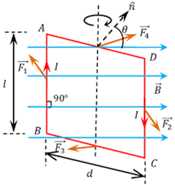
Then Force on Side BC and DA will be equal and opposite as their currents are in opposite directions. There is no net force and torque due to force on side BC and DA as these forces are collinear along the axis and hence cancel each other.
Force on arm AB and CD are F1 and F2, They too are equal and opposite in magnitude but they are not collinear and hence constitute a torque.
The torque on the loop, in this case, is however less than the torque when the loop was placed in the plane of the magnetic field B.
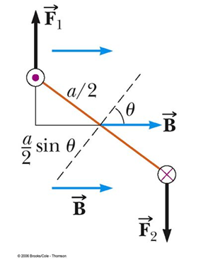
When angle ‘θ’ tends to zero, the perpendicular distance between them also approaches zero, Thus making the force collinear and the net force and net torque zero.
For N turns
Also,
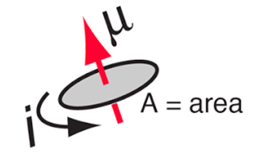
Where m= NIA magnetic moment of N turns coil.
Magnetic moment is a measure of an object's tendency to align with a magnetic field. It is a vector quantity.
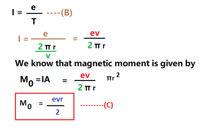
The Magnetic dipole Moment of revolving electron
In Bohr’s Model of atom, electrons revolve in circular orbits around the positively charged nucleus under electrostatic force just the way planets revolve around the sun under gravitational force.
Thus the electrons of charge (-e) perform uniform circular motion around a stationary heavy nucleus (+Ze), This constitutes a current ‘I’.
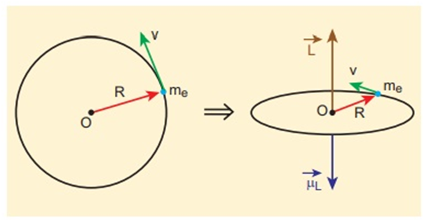
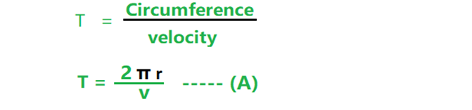
The time period of the electron around circular orbit with uniform speed ‘v’ is given by
The circulating current ‘I’ is given by
Moving coil galvanometer
Moving coil galvanometer is an instrument used for deflection and measurement of small electric currents and voltages.
Principle: It is working is based on the fact that when a current-carrying coil is placed in a magnetic field. It experiences a torque.
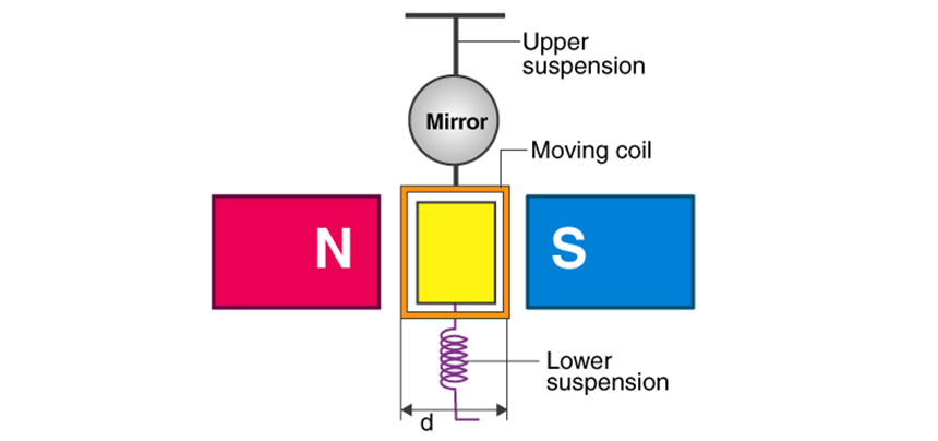
- Moving coil galvanometer consists of a coil with many turns, free to rotate about a fixed axis in a uniform radial magnetic field.
- There is a cylinder with a soft iron core which not only makes the field radial but also increases the strength of the magnetic field.
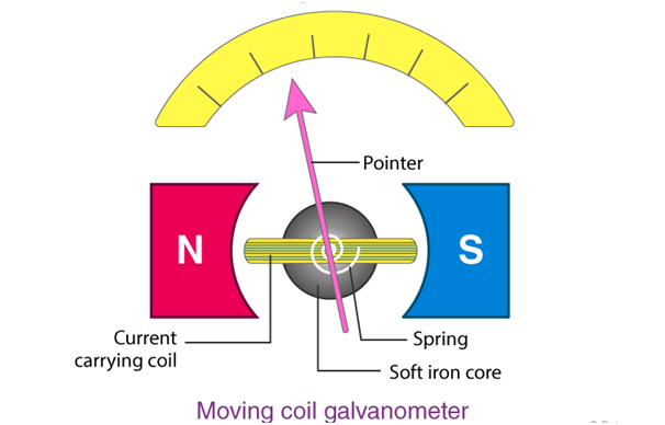
- When current flows through the coil, torque NIBA acts on it. The magnetic torque tends to rotate the coil by angle Φ. The spring provides counter-torque kΦ that balances the magnetic torque NIAB, resulting in angular deflection Φ.
- In equilibrium KΦ= NIBA, where K= torsional constant of spring ( restoring torque per unit twist)
- Deflection Φ= (NAB/k) *I, Thus deflection is directly proportional to the current in the coil so it is used to detect and measure currents.
- Deflection per unit current (Φ/ I)= NAB/k is called the sensitivity of the galvanometer.
- A convenient way to increase the sensitivity of the galvanometer is to increase the number of turns.
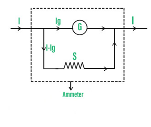
Galvanometer as an ammeter and Voltmeter
A Galvanometer can be used as an ammeter to measure the value of the current.
- For measuring currents, the galvanometer has to be connected in series but the resistance of the galvanometer is very high, this will change the current in the circuit.
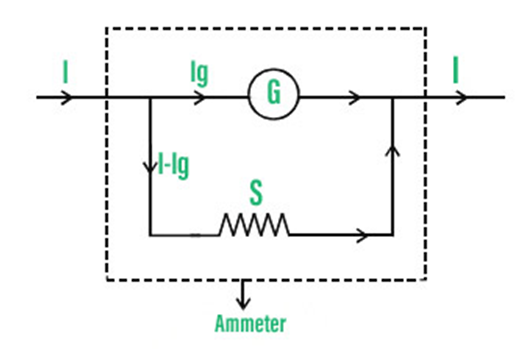
- To overcome this situation a shunt resistance ‘S’ is attached parallel to the galvanometer coil to drastically reduce the resistance of the galvanometer.
- The scale of this ammeter is calibrated and graduated to read off the current values.
The galvanometer can be used as a voltmeter to measure the voltage across a given section of the circuit.
- For this galvanometer must be connected parallel with the section of the circuit whose potential difference is to be measured.
- It must draw a very small current from the circuit, otherwise it will disturb the original voltage.
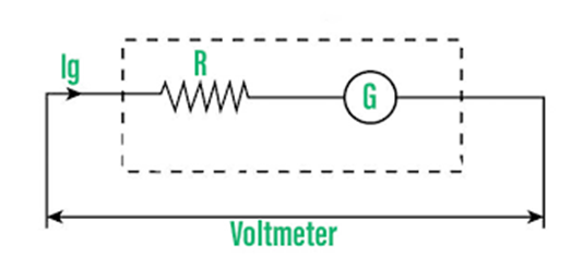
- To ensure that the voltmeter draws negligible current from the circuit, the resistance of the voltmeter must be very high. Therefore a very high resistance is connected in series with a galvanometer to make it work like a voltmeter.