 Grow Career Publication
 Madhava Publications
- Books Name
- Physics by Anshu Physics Book
- Publication
- Madhava Publications
- Course
- CBSE Class 12
- Subject
- Physics
INTRODUCTION:
In 1942, a German Physicist Kirchhoff extended Ohm’s law to complicated circuits and gave two laws, which enable us to determine the current in any part of a complicated circuit easily in an organized way. But before jumping to the topic, let me first introduce some terms that may be used in later topics.
- Electrical network: The term electric network is used for a complicated system of electrical conductors. The above circuit is an electrical circuit.
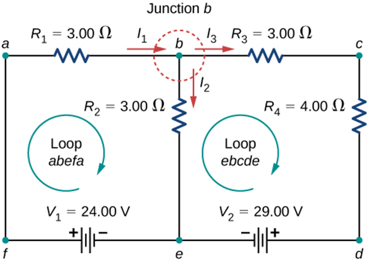
- Junction: Any point in an electrical circuit where two or more conductors are joined together is a junction. In above circuit b, e are junctions.
- Loop and Mesh: Any closed conducting path in an electric network is called a loop or mesh. In the above circuit, we have two loops, loop abefa and ebcde.
- Branch: A branch is any part of a network that lies between two junctions. In the above circuit ab, bc, cd etc are branches
Kirchhoff’s Law - When we have complicated circuits and use of ohm’s law and formulae for series and parallel connection of resistors to solve the circuit are not very helpful. Kirchoff’s law became the savior for such circuits.
There are two laws of Kirchoff's
- Kirchhoff's Voltage Law (KVL) also called the loop law
- Kirchhoff’s Current Law ( KCL ) also called junction law
Kirchhoff’s Current law ( KCL) - Kirchhoff’s current law states that in an electric circuit, the algebraic sum of current at any junction is zero.
The Sum of currents entering a junction is equal to the sum of currents leaving that junction.
Mathematically, this law can be explained by
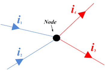
Here you can see that currents in blue colors‘ i1 ‘ and ‘i2’ are incoming currents and currents in the red colors ‘i3’ and ‘i4’ are outgoing
Currents.
So according to KCL, i1 + i2= i3+ i4
Let's see some other examples and try to learn from them.
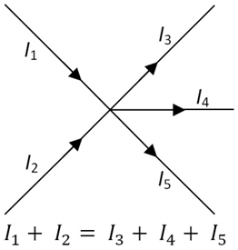
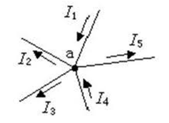
here , I1+ I4= I2 + I3+ I5
I hope with the above examples you have got a better understanding of Kirchhoff's Current Law.
You can also imagine a pipe in which water is flowing, Just like at any place inside the pipe the amount of water coming will be the amount of water going and there is not anything like pilling of water happening inside it. It's just flowing.
In the same way, when charges move inside a conductor, we expect the same ‘ no pilling of charge happens at any point in the circuit’. This is actually the cause of Kirchhoff's current law.
Kirchhoff’s Voltage Law ( KVL) - Kirchhoff’s Voltage Law states that around any closed loop of a network. The algebraic sum of the change in the potential must be zero.
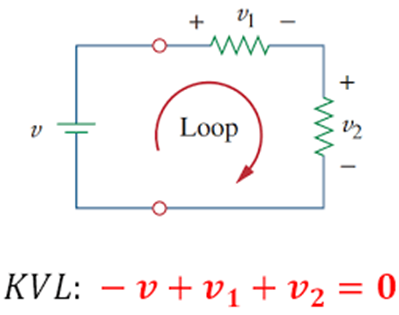
In another word, The Algebraic sum of the emfs in any loop of a circuit is equal to the product of currents and resistances in it.
Mathematically,
The sign convention used in Loop Law ( KVL)
We have to assign a loop current for every loop, we can take any direction as the direction of traversal.
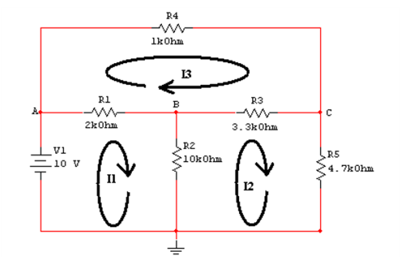
Like in the circuit given below, we have three loops and hence three-loop currents. The direction of all the loops is taken clockwise in the figure given below. The direction of the loop can be anything
- All loops in a clockwise direction
- All loop in an anticlockwise direction
- Some in clockwise and some in an anticlockwise direction.
Like in the circuit given below, we have three loops and hence three-loop currents. The direction of all the loops is taken clockwise in the figure given below.
In the figure given below, the direction of the loop in loop 1 is clockwise and the direction of the loop is anticlockwise in the second loop.
- The emf of the cell is taken to be positive if the direction of traversal is from the negative to positive terminal ( rise in potential ).
- Emf would be taken negatively if the direction of traversal is from positive to negative.
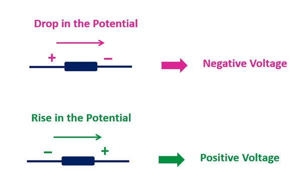
- The current-resistance product ( IR) is taken to be positive if the resistor is traversed in the same direction of the assumed current. ( loop current)
- IR would be negative if the resistor is traversed in the opposite direction of the assumed current.
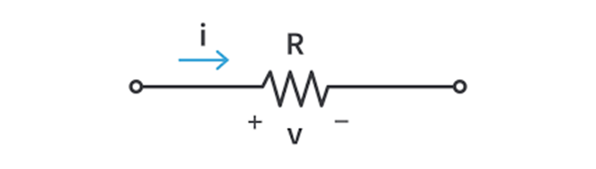
In the above figure if the direction of traversal is the same as the current ( Left to right ) then V= IR would be positive and if the direction of traversal is opposite to assumed current “I” then V= -IR.
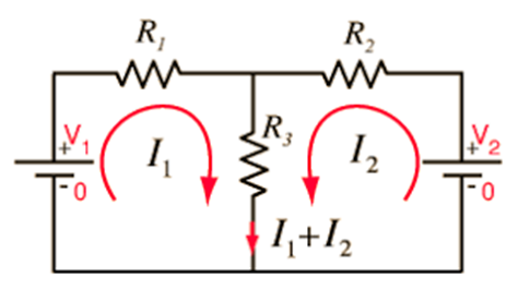
Example - Let's take an example of an electric circuit with two loops. We will apply the above information and try to form the two-loop equations.
In the figure given below, we have two loops. Let's assume that the direction of both loops is clockwise with loop current I1 and I2 respectively.

Let's start to move in loop one abefa in the direction of the loop with loop current I1,
- In the branch, ‘ab’ potential drop across R1 would be written as + I1 *R1 as we are moving along the assumed current I1.
- In the branch ‘be’’, we encounter resistance R2. The potential drop across R2 = + I2*R2 as we are moving along the assumed current I2 in this branch.
- Now in the branch ‘ef’, we encounter an emf source and we are moving from its negative terminal to a positive terminal ( rise in potential so emf would be taken positive( + V1). In branch ‘fa’ there is nothing so leave it.
Now if we use all the above information in the equation
Then we will have + V1= +I1*R1 + I2*R2 as the equation of first loop + 24 = 3* I1+ 3* I2 ………(1)
Let's move to the second loop ‘bcdec’, notice that the current in-branch bc, cd, de is I3 and current in-branch be is I2.
- As we move in-branch bc, voltage drop through R3 will be +I3*R3 and in-branch cd, Voltage drop through R4 will be + I3*R4, as in both the branches we are moving along the assumed current I3.
So the equation for branch bcd will be I3*R3 + I3*R4.
- Now in branch ‘de’ we encounter a battery V2, and while moving from d to e, we are going from the positive terminal of the battery to the negative terminal ( drop-in potential) hence emf would be taken as negative ( -V2).
- In branch ‘eb’ we are going from e to b, but current I2 ( b to e) is opposite to the direction of traversal, So the voltage across R2 in loop 2 will be -I2*R2
If we now combine all information in the equation
We will get -V2 = I3*R3 + I3*R4 -I2*R2
Or , -29 = I3* 3 + I3* 4 - I2*3 = I3 ( 3+ 4) -I2*3
-29= 7*I3 - 3*I2 ………..(2)
Since we have three variables I1, I2, and I3 so we must have 3 equations to solve these variables, we have already got 2 equations.
We can get the third equation by applying KCL at junction b.
At Junction b, I1= I2 + I3 ……. (3)
So, now you can use these three equations and solve for three currents I1, I2, I3 and then you would be able to tell the value of current, voltage drop and direction of current through each resistor.
Wheatstone Bridge - Wheatstone bridge is an application of Kirchhoff’s Law.
This bridge consists of 4 resistance P, Q, R and S and across one pair of diagonally opposite points ( say AC), a source E is connected. For simplicity, we assume that the internal resistance of the source is zero. And between the other two vertices ( BD) a galvanometer G ( a device to detect current ) is connected. Let G be the resistance of the galvanometer and Ig current passes through it
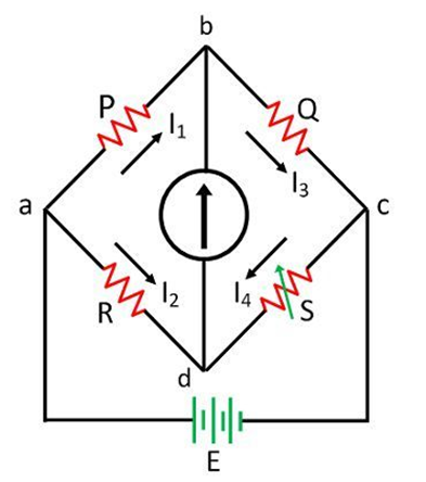
Current I1, I2, I3, and I4 flow through resistors P, R, Q and S respectively, and Ig is the current through the galvanometer.
We can change the resistance of S. There will be one special situation when the galvanometer will show zero deflection and current through it Ig=0. This is called the balanced condition of the galvanometer.
We can use the Kirchhoff laws and use Ig= 0 in that, when we do that we will have a special result about values of resistances P, Q, R and S.
When P / Q = R / S ,
The Wheatstone bridge will be balanced and Ig=0, no current will pass through the diagonal branch and the galvanometer will show no deflection.
Application of Wheatstone bridge - Wheatstone bridge and its balance condition provide a practical method of finding the unknown resistance.
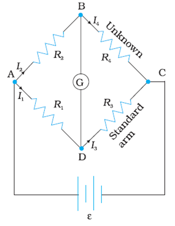
Here resistance R4 is unknown, When we put known resistances R1 and R2 in their places as shown and R3 here is standard resistance whose value can be varied. We go on varying R3 till the galvanometer shows a null deflection and the Wheatstone bridge is in balanced condition.
The resistance of R3 at that time is noted and we can use the condition of a balanced Wheatstone bridge to find the resistance of R4.
R4= R3 ( R2/R1).
Meter bridge - Meter bridge works on the principle of Wheatstone bridge. But the difference is that the two resistances R1 and R2 in the Wheatstone bridge are replaced by a wire of uniform cross-section and of length one meter. That’s why it is called the Meter bridge.
This wire is stretched tight and clamped between two thick metallic strips bent at right angles.
The metallic strips have two gaps ( G1 and G2) across which the two resistors ( P, Q) can be connected. The endpoints ( A and B) where the wire is clamped are connected to a cell through a key.
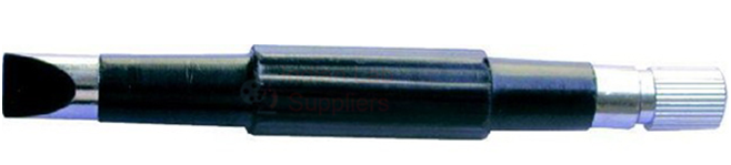
One end of the galvanometer is connected with the metallic strip midway in between the two gaps( point E). The other end of the galvanometer is connected with the jockey ( J)
A jockey is essentially a metallic rod whose one end is a knife-edge that can slide over the wire of a meter bridge to maintain an electrical connection.
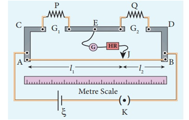
Suppose P is an unknown resistance and Q is known resistance. When we slide the jockey on the wire. On a particular point of the wire, the galvanometer will show null deflection and the meter bridge is in a balanced condition.
Let ‘L1’ be the length of the wire from A to the null point on the wire.
And L2 is the length of wire from B to the null point of the wire.
We know L1 + L2= 1 m = 100 cm
So L2= 100- L1
The four resistance of the bridge in balanced conditions are P, Q, RcmL1 and Rcm(100-L1), where Rcm is the resistance of wire per unit cm.
So, according to the principle of the Wheatstone bridge
P/Q= Rcm*L1 / ( Rcm*(100-L1)
Therefore, P/Q= L1/(100-L1)
So unknown resistance P= Q * L1/ (100-L1)
Where L1 = balanced length of wire from A in cm.
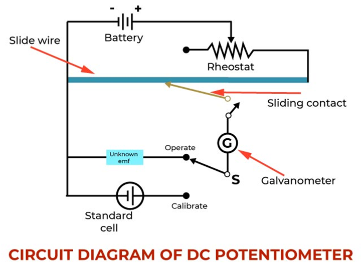
Potentiometer - This is an ideal voltmeter that does not change the original potential difference and still can measure potential difference and also doesn't need to have infinite resistance.
Construction: It is basically a long piece of uniform wire sometimes a few meters in length across which a standard cell is connected. Usually 1 m long wires are fixed on a wooden board parallel to each other. These wires are joined in series by thick copper trips. Then ends of the wire are connected with a battery, a key K and a rheostat. This circuit is called a driving circuit that sends a constant current I through the wire AB. Thus potential difference gradually falls from A to B. A jockey can slide along the length of the wire.
The principle “ When a constant current flows through a wire of uniform cross-section area and composition, the potential drop across any length of the wire is directly proportional to that length.
Where K= proportionality constant called potential gradient.
By ohms law we have
By comparing equations 1 and 2 we can conclude that
Potential gradient -The potential drop per unit length of a potentiometer wire is called the potential gradient.
S.I unit is V/m but the practical unit is V/cm
Sensitivity of the potentiometer is its capability of measuring a very small potential difference and shows a significant change in balancing length for a small change in the potential difference is measured.
How we can increase the sensitivity of the potentiometer:
- For a given potential difference sensitivity can be increased by increasing the length of the potentiometer wire
- For a potentiometer wire of fixed length, the potential gradient can be decreased by reducing the current in the circuit with the help of a rheostat.
Application of potentiometer
1 . comparison of emf’s of two primary cells.
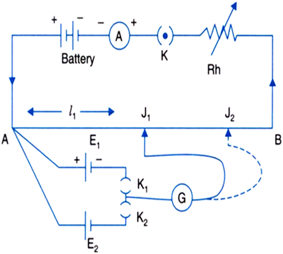
For the comparison of the emf’s of the two cells, the circuit above will be used. Here E1 and E2 are the emf’s of the two cells. Suppose when key K1 is closed and K2 is open and jockey J is moved on the wire AB, the balancing length corresponding to E1 will be ‘L1’.
Now when K2 is closed and K1 is open, the balancing length corresponding to cell E2 is ‘L2’.
From 1 and 2 we have
If emf of one cell is known and emf of another cell is known then we can find the unknown emf of the cell.
2. To find the internal resistance of the primary cell
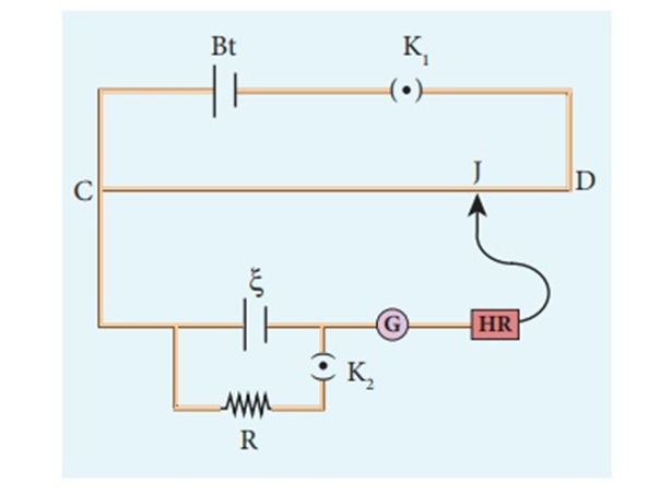
Using the above circuit we can find the internal resistance of the cell.
Close the K1 and keep the Key 2 open and move the jockey on the potentiometer wire. Suppose you get balancing length ‘L1’ corresponding to the emf of cell E
Now close both key K1 and k2 and move the jockey on the potentiometer wire and let you get a balancing length ‘L2’ corresponding to potential drop V
From 1 and 2
From Ohm’s law, we know that
Comparing 3 and 4 we get
Therefore
Equation 5 is used to find the internal resistance of the cell using a potentiometer.