 Grow Career Publication
- Books Name
- Physics Book Part l and ll
- Publication
- Grow Career Publication
- Course
- CBSE Class 12
- Subject
- Physics
Chapter 10: Wave optics

Huygens Principle and Addition of Waves
Defining the Huygens Principle
Huygens principle proposed by Christiaan Huygens In 1678 revolutionized our understanding of light and its characteristics. You may be familiar with the rectilinear theory of light that purports that light travels along straight paths. Huygens principle is one of the key methods for studying various optical phenomena. The principle is a method of analysis applied to problems of wave propagation both in the far-field limit and in near-field diffraction and also reflection.
Primary and Secondary Sources
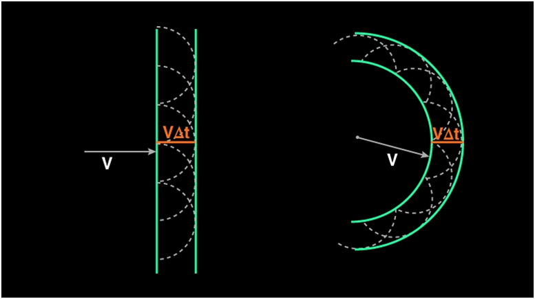
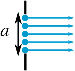
Huygens stated that light spread out like a wave along with all directions from a source. The locus of points that travelled some distance during a fixed time interval is called a wavefront. Thus, from a point source of light, the locus of points that light has travelled during a fixed time period is a sphere (a circle if you consider a 2D source).After the primary wavefront is created, a secondary wavefront is created from every primary wavefront. Secondly, every point on the wavefront acts as a secondary source of light that emits more wavefronts. The net effect is that the effective wavefront generated is tangential to all the secondary wavefronts generated by the secondary sources as shown in the figure.
Advantages:
- Huygens concept proved the reflection and refraction of light.
- The concepts like diffraction of light, as well as interference of light, were proved by Huygens.
Disadvantage:
- Concepts like emission of light, absorption of light and polarization of light were not explained by Huygens principle.
- Huygens principle failed to explain the photoelectric effect.
Reflection of a plane wave using Huygens Principle
As discussed earlier, when light is incident on the surface it is re- emitted without any change in the frequency. This re-emitted light which is returned into the same medium from which it comes out is called Reflection of Light. Consider the figure given below:
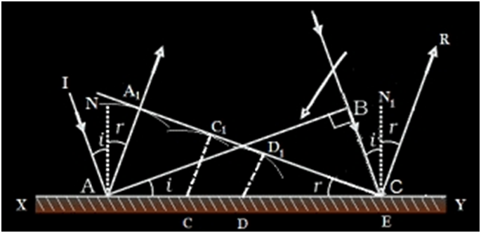
Imagine incoming rays are incident on a surface. Here the wavefronts are plane waves. In plane wavefront, the wavefronts will be infinite parallel planes to each other with constant amplitude. Consider the plane wave AB which falls on the reflecting surface. AB is the incident wavefront and is drawn as perpendicular to the incident ray. It falls at an angle I on the surface. Now according to the Huygens’s principle every point on AB act as a source of secondary wavelets. Consider the points A and B as new sources which emits the secondary waves. The velocity of the propagation of waves is ‘v’. Let ‘t’ be the time taken. So let’s assume that vt be the distance moved by the secondary wavelets. AA1 and BE are the secondary waves. Now the new wavefront should be a tangents line which connects those two secondary waves. The reflected waves should be perpendicular to the new wavefront. A1E is the new tangential line which connects the secondary wavelets.
Consider ΔABE and ΔAA1E. Here AE is common.
<B = <A1 = 90° .
AA1 = BE.
These triangles are congruent triangles
So <I = <r
Thus Angle of Incidence = Angle of Reflection. This is the first law of reflection.
The doppler effect
we should mention here that one should be careful in constructing the wave fronts if the source (or the observer) is moving. For example, if there Is no medium and the source moves away from the observer, then later wave fronts have to travel a greater distance to reach the observer and hence take a longer time. the time taken between the arrival of two successive wave fronts is hence longer at the observer than it is at the source. thus, when the source moves away from the observer the frequency as measured by the source will be smaller. this is known as the doppler effect.
COHERENT AND INCOHERENT ADDITION OF WAVES
The sources and the waves are said to be coherent if they have the same frequencies, same wavelength, same speed, almost same amplitude and have no phase difference or a constant phase difference. If any of the properties is lacking, the sources are said to be incoherent.
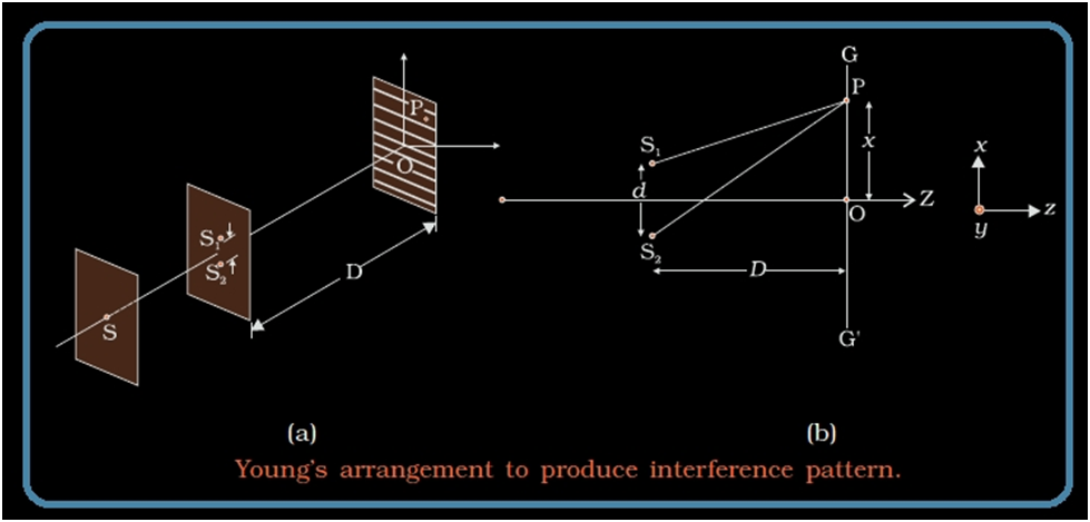
The examples of the coherent sources and the waves are sound waves from two loud speakers driven by the same audio oscillator, electromagnetic waves from two microwaves horns driven by the same oscillator, light waves generated by Young double-slit experiment, light waves coming from a laser gun.
Let for any other arbitrary point the phase difference between the two displacements produced by the waves y1 and y2 be φ.
Thus, if the displacement produced by y1 is given by
y1=acos(ωt)
then, the displacement produced by y−2 would be
y2=acos(ωt+ϕ)
and the resultant displacement will be given by
y=y1+y2
y=a[cosωt+cos(ωt+φ)]
y=2acos(φ/2)cos(ωt+φ/2)
[∵cosA+cosB=2cos(A+B2)cos(A−B2)]
The amplitude of the resultant displacement is 2a cos (φ/2) and therefore the intensity at that point will be if the waves have the same intensity Io
I=4Iocos2(ϕ2)
If the waves are of different intensities, then the resultant intensity is given by
I = I1 + I2 + 2 √(I1 I2 Cos Θ), where Θ is the phase difference between two waves. For the constructive interference the value of Θ = 0°, so that the Cos Θ = 1 and for the destructive interference the value of Θ = 90°, so that the Cos Θ = 0.
In case of the incoherent sources or waves we can have the intensity simply by algebraic method that means I = I1 + I2.
Intensity of light at the point of Interference
We know that intensity of any light wave is directly proportional to the square of its amplitude. In case of coherent sources, let’s consider the factor of frequency to be a constant. Thus the intensity for the wave is considered as KA2.
I = KA2, where K is the constant which depends on what medium the wave is in.
Consider the resultant amplitude as ‘R’ at the point of interference. Now the resultant intensity at this point can be written as
IR = KR2
= K [A12 + A22 + 2A1 A2 Cos ϕ]
= KA12 + KA22+ 2KA1 A2 Cos ϕ
Substitute KA12 = I1 and KA22 = I2
Thus IR = I1 + I2 + 2 √(I1 I2 Cos ϕ)
So the resultant intensity of two waves after the interference phenomenon is
IR = I1 + I2 + 2 √(I1 I2 Cos ϕ)
Here ϕ is the phase difference between two waves.
In case of constructive interference, the value of ϕ =0 and so Cos ϕ =1.Then IR = I1 + I2 + 2 (√I1 I2 = (√ I1 + √I2)2 where the waves are superposed in same phase. Here the resultant intensity is maximum. For destructive interference, the waves superpose in opposite direction. Then Cos ϕ = -1 Thus the resultant intensity is minimum. So, IR = I1 + I2 - 2 √( I1 I2 = (√I1 - √I2)2.
Interference of equal Intensity waves
As mentioned earlier, the resultant intensity of waves at the point of interference
IR = (I1 + I2 + 2 √(I1 I2 Cos ϕ). Let us consider that the two waves have same and equal intensity, which means I1 = I2= I0.
Thus IR = 2I0 + 2I0 Cos ϕ
= 2I0 (1+ Cos ϕ)
1+ Cos ϕ = 2cos2 ϕ/2 (Cos ϕ in half angle form)
Then IR = 4I0 cos2 ϕ/2.
Hence for constructive interference, intensity will be maximum, IR = ( √I1 + √I2)2 = 4 I0.
For destructive interference, the intensity is minimum and IR = (√I1 - √I2)2 = 0.
Diffraction
If the wave travels at an angle theta,θ from the normal to the slit, then there is a path difference x,x between the waves produced at the two ends of the slit.
X, equals, a, sine, theta.
X=asinθ
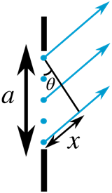
The path difference between the top and middle waves is then
x′=a/2sinθ
If the path difference between the top and middle waves is 2/λ, then they are exactly out of phase and cancel each other out. This happens to all consecutive pairs of waves (the ones produced by the second source from the top and the second source past the middle etc.) at this angle, so there is no resultant wave at this angle.
λ=asinθ
Now the slit can be divided into four equal sections and the pairing of sources to give destructive interference can be repeated for the top two sections, which is identical to the result of pairing off matching sources in the bottom two sections. In the case, we obtain for a minimum (since every pair of waves we consider will destructively interfere due to our choice of geometry and pairing),
λ/2=4asinθ
We can then divide the slit aperture into six equal sections, and pair off sources in the top two divisions, then the middle two divisions, and then the bottom two, to give destructive interference for every matched pair. The minima of intensity are obtained at anglesn, lambda,
N λ=a sin θ
where n,n is an integer n, equals, 0,n=0. There is a maximum of intensity in the centre of the pattern.
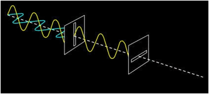
What is Polarization
In Physics, is defined as a phenomenon caused due to the wave nature of electromagnetic radiation. Sunlight travels through the vacuum to reach the Earth, which is an example of an electromagnetic wave. These waves are called electromagnetic waves because they form when an electric field that interacts with a magnetic field. In this article, you will learn about two types of waves, transverse waves, and longitudinal waves. You will also learn about polarization and plane polarised light.
Transverse waves
Transverse waves are waves, movement of the particles in the wave is perpendicular to the direction of motion of the wave. Longitudinal waves are when the particles of the medium travel in the direction of motion of the waves.
Light is the interaction of electric and magnetic fields travelling through space. The electric and magnetic vibrations of a light wave occur perpendicularly to each other. The electric field moves in one direction and magnetic in another though always perpendicularly. So, we have one plane occupied by an electric field, the magnetic field perpendicular to it, and the direction of travel which is perpendicular to both. These electric and magnetic vibrations can occur in numerous planes. A light wave that is vibrating in more than one plane is known as unpolarized light. The light emitted by the sun, by a lamp or a tube light are all unpolarised light sources. As you can see in the image below, the direction of propagation is constant, but the planes on which the amplitude occurs is changing.