 ACME SMART PUBLICATION
1. General characteristics of solid state
- Books Name
- ACME SMART COACHING Chemistry Book
- Publication
- ACME SMART PUBLICATION
- Course
- CBSE Class 12
- Subject
- Chemistry
Chapter 1
solid state
Solids are characterised by the state of matter in which particles are closely packed and held together by strong inter molecular attractive force.
General Characteristics / Properties of Solids
(a) In solid state the particles are not able to move randomly.
(b) They have definite shape and volume.
(c) Solids have high density.
(d) Solids have high and sharp melting point which is depend on the strength or value of binding energy.
(e) They are very low compressible.
(f) They show very slow diffusion.
2. Amorphous and crystalline solids
- Books Name
- ACME SMART COACHING Chemistry Book
- Publication
- ACME SMART PUBLICATION
- Course
- CBSE Class 12
- Subject
- Chemistry
Types of Solids (Amorphous/Crystalline)
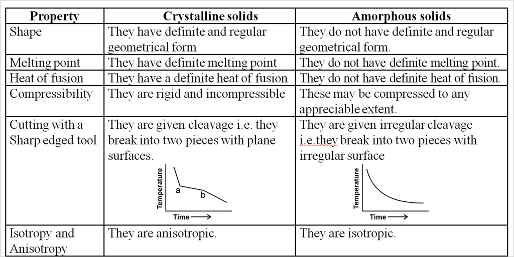
Crystalline solids :
(a) In this type of solids the atoms or molecule are arranged in a regular pattern in the three dimensional network.
(b) They have well defined geometrical pattern, sharp melting point, definite heat of fusion and anisotropic nature.
(c) Anisotropic means they exhibit different physical properties in all directions.
e.g. The electrical and thermal conductivities are different directions.
(d) They are generally incompressible.
(e) The general examples of crystalline solids are as Quartz, diamond etc.
Amorphous Solids :
(a) In this type of solids, the arrangement of building constituents is not regular.
(b) They are regarded as super cooled liquids with high viscosity in which the force of attraction holding the molecules together are so great, that the material becomes rigid but there is no regularity in structure.
(c) They do not have sharp melting points.
(d) They are isotropic as they exhibit same physical properties in all the directions.
(e) The general examples of this solids are as glass, Rubber, plastics etc.
Difference between crystalline and amorphous solids :
3. Classification of crystalline solids
- Books Name
- ACME SMART COACHING Chemistry Book
- Publication
- ACME SMART PUBLICATION
- Course
- CBSE Class 12
- Subject
- Chemistry
Classification of crystalline solids
STUDY OF CRYSTALS :
Crystal : A crystal is a homogeneous portion of a solid substance made by regular pattern of structural units bonded by plane surface making definite angles with each other.
Space lattice : The arrangement of constituents like atom, ions and molecules in different sites in three dimensional space is called space lattice.
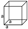
Unit cell : The smallest repeating unit in space lattice which when repeats over and over again, results in a crystal of the given substance called unit cell.
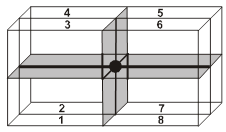
Properties of a cube :
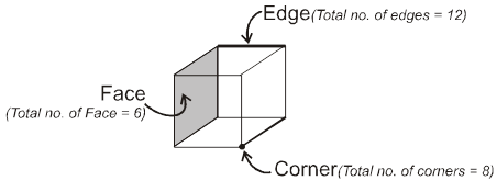
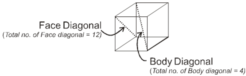

Face : The plane surface of the crystal are called faces.
Edge : An edge is formed by the intersection of two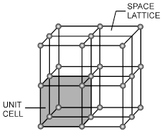 adjacent faces.
Interfacial angles : The angle between the perpendiculars two intersecting faces called interfacial angles.
Unit Cell in two dimensions :
![]()
Now in order to uniquely explain a regular arrangement in two dimensions we need the help of three parameters, two distance parameters and one angular parameter. Based upon their different relationships we can define different cases
Case ‘A’ (a = b) angle = 90º

The unit cell in such a case is a square. such square side by side we will obtain the entire two dimensional arrangement.
Case ‘B’(a ¹ b) angle = 90º

Placing The unit cell formed in this case is a rectangle.
Unit cell in three dimensions :
It has six parameters, 3-distance parameters and 3-angular parameter.
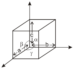
a, b, c are lengths of unit cell (also known as the crystallographic axes). a, b, g are known as the crystallographic angles.
4. Different Classes of Crystals
- Books Name
- ACME SMART COACHING Chemistry Book
- Publication
- ACME SMART PUBLICATION
- Course
- CBSE Class 12
- Subject
- Chemistry
DIFFERENT CLASSES OF CRYSTALS
Based on different permutations of a, b, c and a, b, g we define different crystal classes.
Seven Crystal System
Table : 4
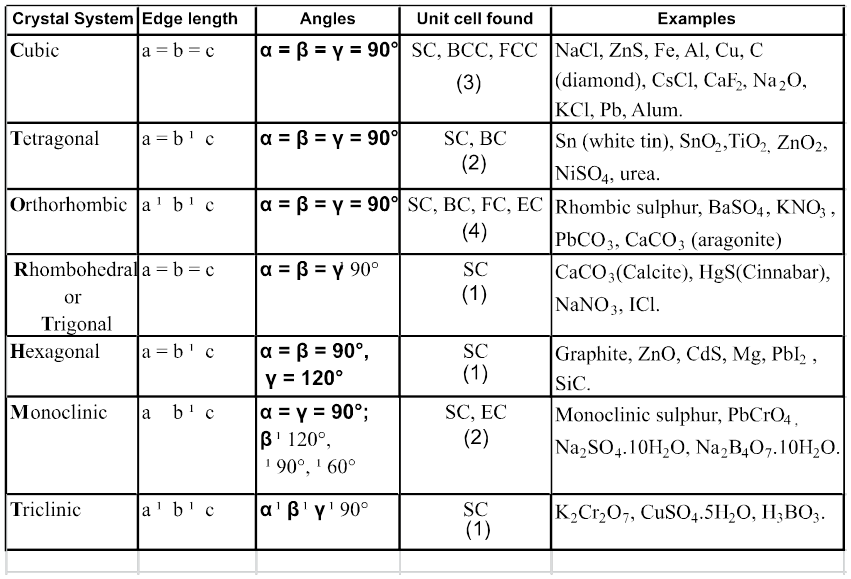
Hint for memorise : CaTORacHMT
Note : In 3-D 14 different types of unit cell are found and these are also known as 14 Bravais lattice.
Types of unit cell :
In every crystal class, the positioning of the lattice points may be different. Based upon these different positions occupied by the lattice points, we have different types of unit cells.
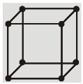
1. Simple / primitive type of unit cell : If lattice points or the particles of the solid are present only at the corners of the unit cell.
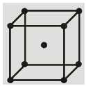
2. Body centred unit cell : lattice point are at the corners as well as at the body centre.
3. Face centred unit cell : lattice points are at corners as well as at each of the face centres.
4. End centred unit cell : lattice points are at the corners as well as at centre of any of two opposite faces.
Each of these arrangements corresponds to a unique and different type of arrangement.These 14 different arrangements are called the 14 Bravais lattices.
In any lattice, the surrounding of each and every lattice point is exactly identical
5. Mathematical Calculations of Cubic System
- Books Name
- ACME SMART COACHING Chemistry Book
- Publication
- ACME SMART PUBLICATION
- Course
- CBSE Class 12
- Subject
- Chemistry
MATHEMATICAL ANALYSIS OF CUBIC SYSTEM
(TYPES AND ANALYSIS)
Simplest crystal is to be studied in cubic system. Three types of cubic systems are following.
(a) Simple Cubic (SC) : Atoms are arranged at the corners of the cube.
(b) Body Centered Cubic (BCC) : Atoms are arranged at the corners and at the centre of the cube.
(c) Face Centered Cubic (FCC) : Atoms are arranged at the corners and at centered of the each faces.
Contribution of different Lattice point in one Cubical unit cell :
(i) Contribution from one corner lattice point =![]() th.
th.
(ii) Contribution from one face centered lattice point =![]() .
.
(iii) Contribution from edge centered lattice point = ![]() th.
th.
(iv) Contribution from body centered lattice point = 1.
Number of atoms per unit cell / unit cell contents :
The total number of atoms contained with in the unit cell for a simple cubic called the unit cell content.
(a) Simple cubic structure (sc) :
Each corner atom is shared by eight surrounding cubes. Therefore, it contributes for ![]() of an atom.
of an atom.
![]()
(b) Body centered cubic structure (bcc) :
(i) Eight Corner atoms contribute one atom per unit cell.
(ii) Centre atom contribute one atom per unit cell.
(iii) So, total 1 + 1 = 2 atoms per unit cell.
![]()
(c) Face centered cubic structure (fcc) :
(i) The eight corners atoms contribute for ![]() of an atom and thus one atom per unit cell.
of an atom and thus one atom per unit cell.
(ii) Each of six face centered atoms is shared by two adjacent unit cells and therefore one face centred atom contribute half of its share. Means
![]() atom per unit cell.
atom per unit cell. 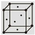
(iii) So, total Z = 3 + 1 = 4 atoms per unit cell.
Atomic radius :
It is defined as the half of the distance between nearest neighbouring atoms in a crystal. It is expressed in terms of length of the edge (a) of the unit cell of the crystal.
(a) Simple cubic structure [S.C.]
Radius of atom ‘r’ =![]()
(b) Face centered cubic structure (FCC) ‘r’ = ![]()
(c) Body centered cubic structure (BCC) ‘r’ =![]()
a = b = c
a = b = g = 90º
6. Arrangement of the atom / particles of the solids in three dimensions
- Books Name
- ACME SMART COACHING Chemistry Book
- Publication
- ACME SMART PUBLICATION
- Course
- CBSE Class 12
- Subject
- Chemistry
Arrangement of the atom / particles of the solids in three dimensions
Now having gained a knowledge of some of the terms, let us study how the different arrangements in space are brought about.
Firstly we will focus our attention on the solids containing only one type of lattice points.
The solids which contain only one type of lattice points are:
- metallic solids (eg. Iron)
- molecular solids (eg. dry ice)
- covalent network solids (eg. diamond)
(Ionic solids do not fall into this category as they contain more than one type of particles,they will be studied in the later parts of the chapter)
All the atoms or particles of the solids will be represented by solid spheres, each of radius ‘r’.
We will be taking these spheres of radius ‘r’ and explore how we can arrange these in three dimensions.Firstly we will begin with arrangement in one dimension.
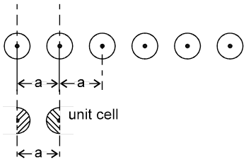
Arrangement in 1-D : In one dimension it is possible to arrange the spheres in two possible ways.
1. 
Not Stable [because the potential energy of the system is not minimum]
2. 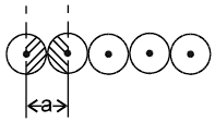 a = 2r
Coordination number = 2
1-D close packing stable arrangement
This is the predominant way of packing in one dimension and as such most of the space lattices will show such an arrangement in one dimension along the planes of close packing.
Arrangement in two dimension :
In two dimensions also there are two ways of packing the spheres(in moving from one dimension to two dimensions it can be imagined that the two dimensional array will be made up of 1-D closed pack arrays / lines which are stacked one on top of other.
1. Square packing : If the one dimensional arrays are placed on top of one another, we get the square packing in two dimensions.
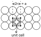
One sphere will be in contact with 4 other spheres.
area of square = a2 = 4r2
area of atoms in the square = ![]()
fraction of area occupied by spheres = 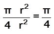 = 78%
= 78%
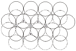
2. Hexagonal close packing : (in 2-D) If in a two dimensional arrangement,every one dimensional array is placed in the cavity of the just preceding array, we get the hexagonal packing in two dimensions.
area of hexagon = ![]()
area of atoms = ![]()
fraction of area occupied =![]()
As is evident from the above calculations, the spheres are in closer contact in the hexagonal arrangement, hence the hexagonal arrangement is considered to be a better way of packing as compared to the square packing.
Arrangement in three Dimensions :
1. Simple cubical arrangement in three dimensions :
(will be made up of 2-D sheets arranged one over other)
The simple cubical packing is obtained by arranging the square pack sheets of two dimension one over the other such that spheres of the second sheet are exactly (vertically) above the spheres of first sheet.
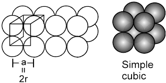
(Note that ![]() , hence crystal thus formed will belong to the cubic crystal class, and as the lattice points are only at the corners, hence the unit cell will be simple, therefore what we get is the simple cubic)
, hence crystal thus formed will belong to the cubic crystal class, and as the lattice points are only at the corners, hence the unit cell will be simple, therefore what we get is the simple cubic)
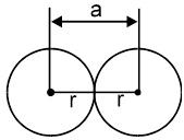
(i) Relation between ‘a’ and ‘r’
a = 2r (because atoms along the edge are touching each other)
(ii) Effective no. of atoms per unit cell :
(Z) = × 8 = 1
(iii) Packing fraction :
Packing efficiency = ![]()
=  = 0.52 (or 52%)
(Note : This is not a very efficient way of packing as the packing fraction is very low)
(iv) Coordination Number :
It is defined as the number of atoms touching any one particular atom. For simple cubic, coordination number = 6.
(v) Density of unit cell : It is the ratio of mass of the spheres present in unit cell and total volume of unit cell.
Density of the unit cell = ![]()
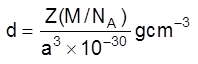 Þ
Þ 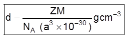
Where Z = no. of atoms in a unit cell
M/NA = mass of a single atom
M = molar mass
NA = Avogadro number (6.023 × 10²³)
2. Body centred cubic :
The body centred cubic is a unique way of packing, as the 2D-arrays that can be imagined to constitute the space lattice are themselves formed in a unique way. The lattice points in the 2D array do not touch each other. The spheres start touching each other only upon moving from 2D to 3D, i.e when the 2D arrays are placed on top of each other in such a fashion that the spheres of the next plane are into the cavities of the first plane of spheres.The third plane of spheres is then exactly identical to the first plane of spheres.
(i) a ¹ 2r (as atoms along the edge are not touching each other)
they touch along the body diagonal, hence ![]() a = 4r.
a = 4r.
(ii) Effective number of atoms (Z) = 1 + ![]() × 8 = 2.
× 8 = 2.
(iii) Packing fraction = 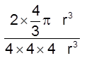
![]() =
=  0.68 = 68%
(iv) Coordination No.= 8
(the sphere at the body centre will be touching the spheres at the eight corners)
(v) Density =  =
= ![]() (Q Z = 2)
(Q Z = 2)
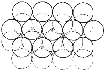
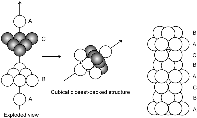
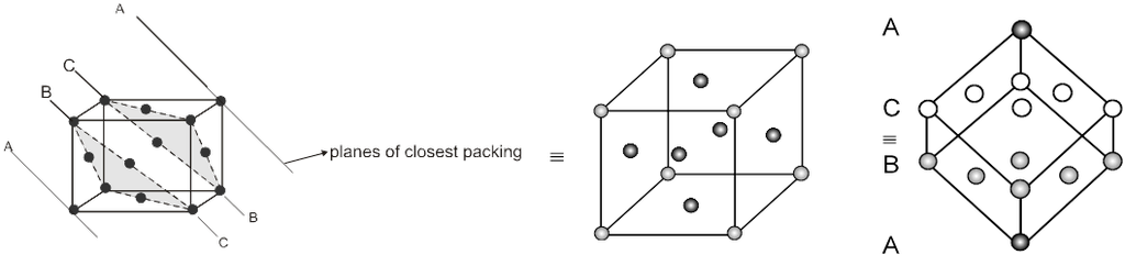
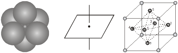
3. Close packing in three dimensions :
(These are made up of two dimensional hexagonally packed sheets) In second layer we have two kinds of voids.
(i) Voids of second layer below which there are spheres of first layer (all voids of type ‘a’).
(ii) Voids of second layer below which there are voids of first layer (all voids of type ‘b’).
For third layer, we have two possibilities.
(A) If spheres of IIIrd layer are placed in voids of IInd layer below which there are spheres of Ist layer (voids of type ’a’) then Ist layer and IIIrd layer are identical so this is called AB–AB pattern repeat or hexagonal close packing)
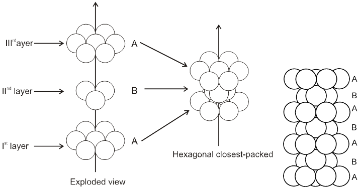
Hcp unit cell : a = 2r = b
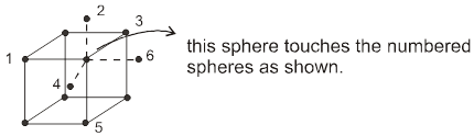
(i) Calculation of ‘c’ :
For the estimation of ‘c’, consider the spheres marked 1,2,3,4 in the unit cell as shown.These four spheres form a regular tetrahedron. The length of the perpendicular from ‘4’ to the equilateral triangle 1-2-3 will be equal to c/2.
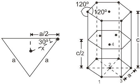
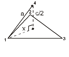 cos 30º =
 ![]()
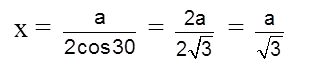
Apply pythagoras theorem.
x2 + (c/2)2 = a2 Þ c = ![]() 4r
4r
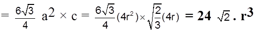
Volume of the hexagon = Area of base x Height.
(ii) Effective no. of atoms per unit cell :
Z = ![]() × (no. of atoms at corner) +
× (no. of atoms at corner) + ![]() × (no. of atoms at face centres) + 1 × (no. of atoms inside the body)
× (no. of atoms at face centres) + 1 × (no. of atoms inside the body)
= ![]() × 12 +
× 12 + ![]() × 2 + 1 × 3 = 2 + 1 + 3 = 6
× 2 + 1 × 3 = 2 + 1 + 3 = 6
Packing fraction :  = 0.74 = 74%
Coordination No. : C.N. = 12
Density ![]() (Q Z = 6)
(Q Z = 6)
(B) ABC-ABC arrangement :
If the third layer spheres are placed in those voids of second layer under which there are voids of the first layer of spheres (voids of type ‘b’), then the first and the third layer of spheres will not be identical.Such an arrangement will lead to an ABC-ABC type of arrangement.It is also known as the cubical close packing (ccp) or also as the Face Centred Cubic structure (FCC).
(a = tetrahedral voids)
(b = octahedral voids)
In the ABC – ABC pattern, the spheres of 4th layer are vertically above the spheres of Ist layer then these consecutive layers are different from each other, fourth layer will be idential to first layer so it will be called ABC – ABC repeat pattern.It is also called the ccp (cubical close packing) because a cubical type of unit cell is used for the study of this arrangement.
(i) Relation between ‘a’ and ‘r’ :
a ¹ 2r
![]() (as the spheres touch along the face diagonal)
(as the spheres touch along the face diagonal)
(ii) Effective no. of atoms :

(iii) Packing fraction : 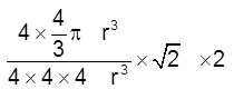 =
= ![]() = 0.74 = 74%
= 0.74 = 74%
(iv) Coordination number : 12
(v) Density![]()
Note : In close packings, whenever two consecutive layers are of different kinds(FCC, HCP) then packing efficiency will always be 74%
7. Types of voids found in close packing
- Books Name
- ACME SMART COACHING Chemistry Book
- Publication
- ACME SMART PUBLICATION
- Course
- CBSE Class 12
- Subject
- Chemistry
TYPES OF VOIDS FOUND IN CLOSE PACKING
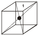
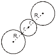
1. Tetrahedral void (3-Dimensional 4 co-ordinate) :
The tetrahedral void is formed whenever a sphere is placed on top of the triangular arrangement as in case of the triangular void.
r = 0.225 R
Location of tetrahedral voids in FCC unit cell :
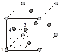
The FCC unit cell has eight tetrahedral voids per unit cell. Just below every cornerof the unit cell, there is one. As there are eight corners, there are eight tetrahedral voids.
The spheres 1, 2, 3, 4 form a tetrahedral void.
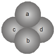
2. Octahedral void (3-Dimensional 6 coordinate void) The octahedral void is formed whenever two spheres are placed, one on top and the other below a square arrangement of spheres
r = 0.414 R 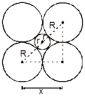
Location of octahedral voids in a FCC unit cell :
In a FCC unit cell, there are four octahedral voids. They are present at all the edge centres and at the body centre. The contribution of the edge centre void per unit cell is ![]() .
.
Hence, total number of octahedral voids =  + (1) = 4
edge centres body centre
Note : Let the no. of close packed spheres be N then the no. of octahedral void gemetrated = N and the number of tetrahedral void generated = 2N
3. Cubical void (3-Dimensional 8-coordinate void)
The cubical void is generally not found in closed packed structures, but is generated as a result of distortions arising from the occupancy of voids by larger particles.
Along body diagonal
r = 0.732 R
IONIC SOLIDS :
Ionic solids are characterised by the presence of atleast two types of particles,viz: the cation and the anion,even the simplest of ionic solids contains one cation and one anion.
The Cations are generally found to be of smaller size, and the anions of larger sizes. The anions thus form the lattice by occupying the lattice positions and the cations are found inside the voids in such structures.
The types of void occupied by the cation would depend upon the the ratio of its radius to that of the anion, popularly termed as the radius ratio. Hence, radius ratio = r+ / r–

Examples of ionic crystals :
(a) Rock Salt (NaCl) Coordination number (6 : 6) NaCl crystallizes in the face centred cubic structure. The chloride ions are present at all the lattice position and the sodium ions occupy all the octahedral voids.
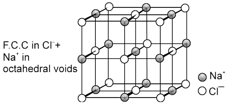
Every sodium is in contact with four chloride ions, and every chloride is in contact with four sodium ions
(b) CsCl C.No. (8 : 8)
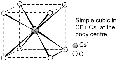
The cesium ion is at the body centre and the chloride ions are at the corners.
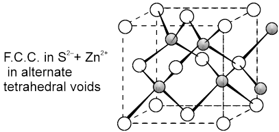
(c) Zinc Blend (ZnS) C.No. (4 : 4)
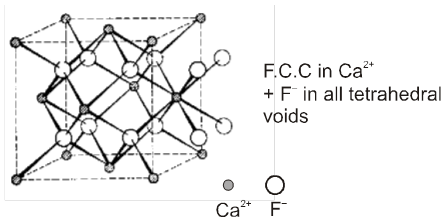
(d) Fluorite structure (CaF2) C.No. (8 : 4)
8. Crystals defects (Point Defects)
- Books Name
- ACME SMART COACHING Chemistry Book
- Publication
- ACME SMART PUBLICATION
- Course
- CBSE Class 12
- Subject
- Chemistry
CRYSTALS DEFECTS (POINT DEFECTS)
Imperfection can be because of :
– Conditions under which crystals have been developed.
– Impurities
– Temp (because of thermal conductivity some atoms/ions can get displaced
These imperfections can be
(a) Point defects – defects will be only at certain lattice positions.
(b) Line defects – If atoms/ions are misplaced/missing/replaced by some other ions along a line
(c) Plane (screw) defects – If atoms/ions are misplaced/missing/replaced by some other ions along a line in a plane.
Types of point defects
Point defect can be classified into three types :
(a) stoichiometric defects
(b) impurity defects
c) non-stoichiometric defect
(a) Stoichiometric defect
These are the point defects that do not distrub the stoichiometry of the solid. They are also called intrinsic ot thermodynamic defects. basically these are two types. Vacancy defecs and interstitial defects.
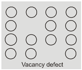
(i) Vacancy defect : When some of the lattice site are vacant, the crystal is said to have vacancy defect. This results in decrease in density of the substance. This defect can also develop when a substance is heated.
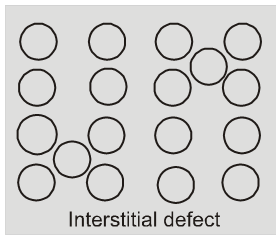
(ii) Interstitial defect : When some constituent particles (atoms or molecules)
occupy an interstitial site. the crystal is said to have interstitial defect. This defect increases the density of the substance.
Vacancy and interstitial defects as explained above can be shown by non ionic solids. Ionic solids must always maintain electrical neutrality.
Rather than simple vacancy or interstitial defects, they show these defects as Frenkel and schottky defects.
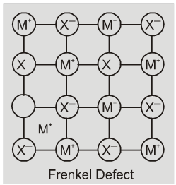
(iii) Frenkel defect : This defect is shown by ionic solids. The smaller ion
(usually cation) is dislocated from its normal site to an interstitial site. It creates a vacancy defect at its original site and an interstitial defect at its new location.
Frenkel defect is also called dislocation defect. It does not change the density of the solid. Frenkel defect is shown by ionic substance in which there is a large difference in the size of ions, for example, ZnS, AgCl,AgBr and AgI due to small size of Zn2+ and Ag+ ions.
Eg. ZnS, AgCl, AgBr, AgI etc.
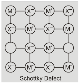
(iv) Schottky defect : It is basically a vacancy defect in ionic solids. In order
to maintain electrical netrality. The number of missing cations and anions are equal.
Like simple vacancy defect, schottky defect also decreases the density of the substance, Number of such defects in ionic solids is quite significant. For example, in NaCl there are approximately 106 schottky pairs per cm3 at room temperature. In 1 cm3 there are about 1022 ions. Thus, there is one schottky defect per 1016 ions. Schottky defect is shown by ionic substance in which the cation and anion are of almost similar sizes. For example,NaCl, KCl, CsCl and AgBr.
Note : It may be noted that AgBr shows both, Frenkel as well as schottky defects.
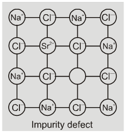
(b) Impurity defects
If molten NaCl containing a little amount of SrCl2 is crystallised, some of
the sites of Na+ ions are occupied by Sr2+. Each Sr2+ replaces two Na+ ions. It occupies the site of one ion and the other site remains vacant. The cationic vacancies thus produced are equal in number is the solid solution of CdCl2 and AgCl.
(c) Non-stoichiometric defect
The defects discussed so far do not disturb the stoichiometry of the crystalline substance. However a large number of non-stoichiometric inorganic solids are known which contain the constituent elements in non-stoichiometric ratio due to defects in their crystal structures. These defects are of two types :
(i) metal excess defect and (ii) metal deficiency defect.
(i) metal excess defect
(a) metal excess defect due to anionic vacancies : Alkali halides like NaCl and KCl show this type of defect. When crystals of NaCl are heated in an atmosphere of sodium vapours, the sodium atoms are deposited on the surface of the crystal. The Cl– ions diffuse to the surface of the crystal and combine with Na atoms to give NaCl. This happens by loss of electron by sodium atoms to form Na+ ions. The released electrons diffuse into the crystal and occupy anionic site. As a result the crystal and now has an excess of sodium. The anionc sites occupied by unpaired electrons are called F-centres (from german word farbenzenter for colour centre). They impart yellow colour to the
crystals of NaCl. The colour results by excitation of these electrons when they absorb energy from the visible light falling on the crystals.
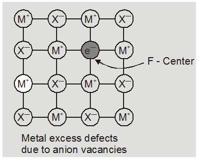
Eg. :
* The excess sodium in NaCl makes the crystal appears yellow.
* Excess potassium in KCl makes it violet.
* Excess lithium in LiCl makes it pink.
Greater the number of F-centres greater is the intensity of colour. This type of defects are found in crystal which are likely to possess schottky Defects.
(b) metal deficiency defect due to the presence of extra cations at interstitial sites : Zinc oxideis white in colour at room temperature. On heating it loses oxygen and turns yellow.
![]()
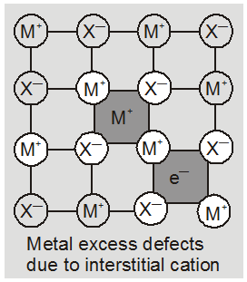
Now there is excess of zinc in the crystal and its formula becomes Zn1+xO. The excess Zn2+ ions move to interstitial sites and the electrons to neghbouring interstitial sites.
(ii) metal deficiency defect : There are many solids which are difficult to prepare in the stoichiometric composition and contain less amount of the metal as compared to the stoichiometric proportion. A typical example of this type is FeO which is mostly found with a composition of Fe0.95O. it may actually range from Fe0.93O to Fe0.96O. In crystals of FeO some Fe2+ cations are missing and the loss of positive charge is made up by the presence of required number of Fe3+ ions.
9. Properties of Solids
- Books Name
- ACME SMART COACHING Chemistry Book
- Publication
- ACME SMART PUBLICATION
- Course
- CBSE Class 12
- Subject
- Chemistry
PROPERTIES OF SOLIDS
1. Electric Properties :
On the basis of electrical conductivity the solids can be broadly classified into the three types:
(a) Metals (conductors)
(b) Insulators
(c) Semi-conductors.
Following are salient features of electrical conductance in solids.
(i) The electrical conductivity of metallic conductors is due to the motion of electrons or positive holes (electronic conductivity) or through the motion of ions (ionic conductivity)
(ii) The conductance through electrons is called n-type conduction and through positive holes is called p-type conduction.
(iii) The conductance in insulators and semiconductors is mainly due to the presence of interstitial electrons and positive holes in the solids due to imperfections.
(iv) The conductivity of semiconductors and insulators increases with increase in temperature while that of metals decreases.
(v) Electrical conductivity of metal is in the order of 106–108 ohm–1 cm–1 while that of inculator is of the order of 10–12 ohm–1 cm–1. Semiconductors have intermediate value in the range 10–9 ohm–1 cm–1.
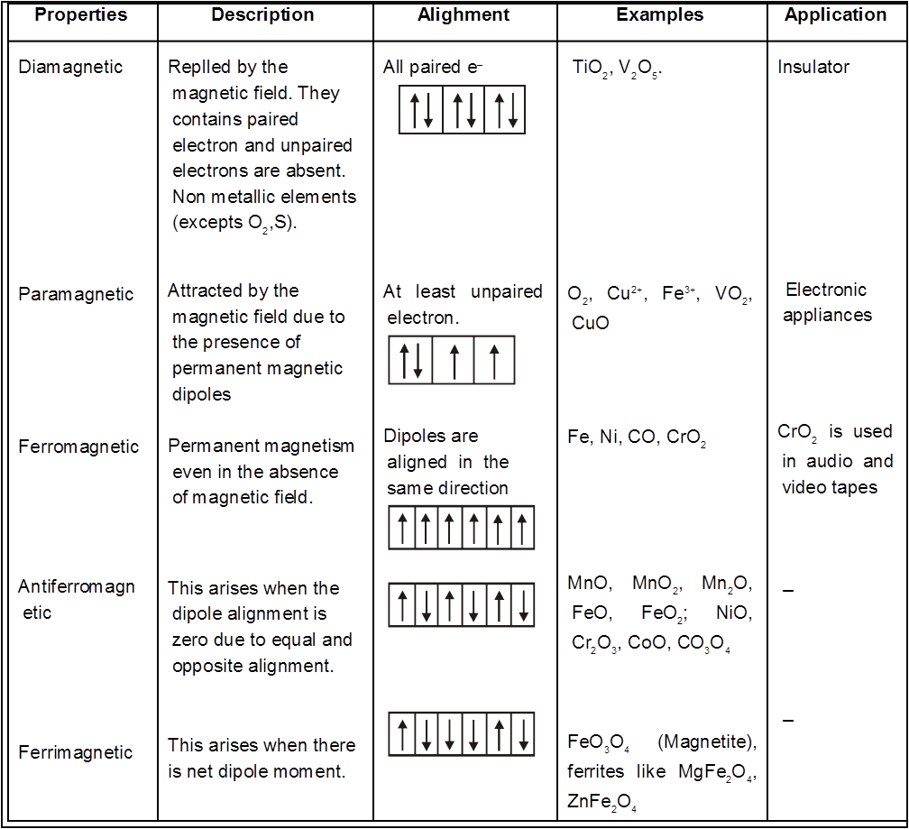
2. Magnetic Properties :
Based on the behaviour of substances when placed in the magnetic field, they are classified into five classes.