 Carrier Point
1. Electric Circuit and Ohm's Law
What is Lorem Ipsum?
Lorem Ipsum is simply dummy text of the printing and typesetting industry. Lorem Ipsum has been the industry's standard dummy text ever since the 1500s, when an unknown printer took a galley of type and scrambled it to make a type specimen book. It has survived not only five centuries, but also the leap into electronic typesetting, remaining essentially unchanged. It was popularised in the 1960s with the release of Letraset sheets containing Lorem Ipsum passages, and more recently with desktop publishing software like Aldus PageMaker including versions of Lorem Ipsum.
1. Electric Circuit and Ohm's Law
- Books Name
- Iti Shree Science Book
- Publication
- Vaishnav Publication
- Course
- CBSE Class 10
- Subject
- Science
Chapter 12
Electricity
Electric current
The flow of electric charge is known as Electric Current. It is expressed in terms of the rate of flow of charges.
The SI unit of electric current is Ampere (A).
The direction of electric current is the same as the direction of positive charges and opposite to the direction of flow of negative charges.
Potential Difference
- Work done per unit charge when taking charge from one point to another is known as the Potential Difference.
- The unit of potential difference is volt (V).
- 1V is defined as the potential difference between two points if 1 Joule of work is done to move 1-coulomb charge from one point to another.
Potential difference (V) between two points = Work done (W)/Charge (Q) V = W/Q
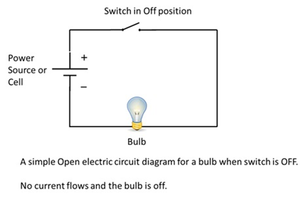
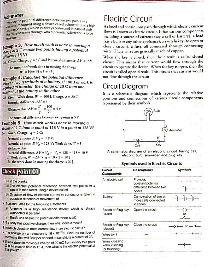
Electric Circuit Diagram
A circuit diagram is a simplified representation of the components of an electrical circuit using either the images of the distinct parts or standard symbols.
An electric circuit is a path through which electric current flows. An electric circuit can also be a closed path, thereby making it a loop. The flow of electric current is possible only when it is a closed circuit. An electric circuit can also be open circuit in which flow of electron is cut because of electric circuit is broken.
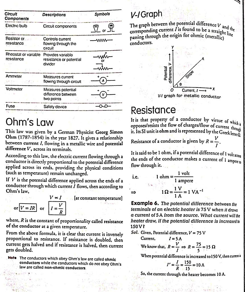
Ohms law
The potential difference between the two points is directly proportional to the current, provided the temperature is constant.
V ∝ l
⇒ V = lR
R is a constant known as Resistance. The SI unit of resistance is the ohm (Ω)
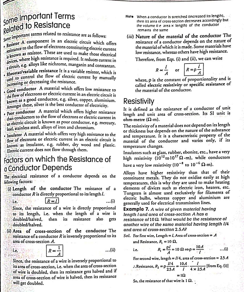
Factors on which resistance of a conductor depends-
- It is directly proportional to the length of the conductor.
- Inversely proportional to the area of cross-section.
- Directly proportional to the temperature.
- Depends on the nature of the material.
Resistivity
Resistivity is the property of the material. The SI unit of resistivity is ohm-metre.
- The resistivity of metals varies from 10-8 to 10-6.
- The resistivity of insulators varies from 1012 to 1017
- Copper and aluminum are used in electrical transmission due to their low resistivity.
- Resistance = Resistivity * Length of Conductor/Cross-Sectional Area
1. Magnetic Field
- Books Name
- Iti Shree Science Book
- Publication
- Vaishnav Publication
- Course
- CBSE Class 10
- Subject
- Science
Chapter 13
Magnetic Effects of Electric current
Magnetic field: The region surrounding a magnet, in which the force of the magnet can be detected, is named as magnetic field.
Magnetic field lines: The magnetic field lines can be explained as imaginary lines that graphically represent the magnetic field acting around a magnet.
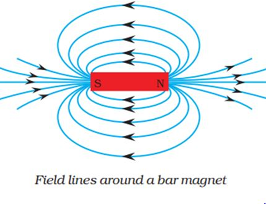
Characteristics of magnetic field lines:
→ The field lines emerge from north pole and merge at the south pole
→ Inside the magnet, the direction of field lines is from its south pole to its north pole.
→ Thus the magnetic field lines are closed curves.
→ Magnetic field lines never intersect with each other.
Properties of magnetic field lines:
→ The tangent drawn to the magnetic field lines gives the direction of the magnetic field.
→ The closeness or density of the field lines is directly proportional to the strength of the field.
→ The field lines emerge from north pole and merge at the south pole.
→ Inside the magnet, the direction of field lines is from its south pole to its north pole.
→ Magnetic field lines form closed curves.
→ Magnetic field lines never intersect with each other.
Field due to a current carrying conductor:
When current is passed through a straight current-carrying conductor, a magnetic field is produced around it.
The magnetic field lines are represented in the form of concentric circles around the conductor.
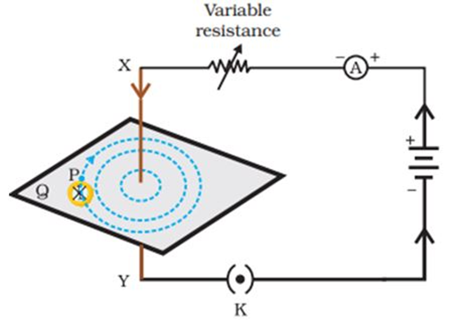
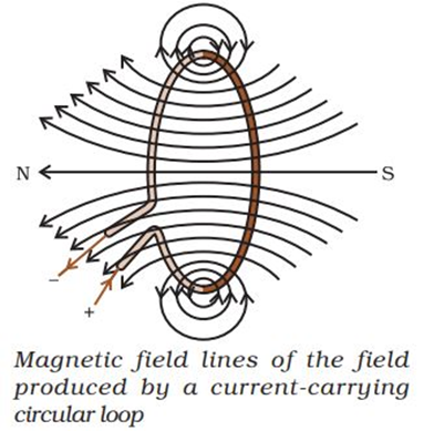
Magnetic field due to current through a circular loop:
→ Every point on the circular loop will act as a straight conductor.
→ Magnetic field lines are closer near the conductor which means the magnetic field is stronger near the periphery of the loop.
→ Magnetic field lines move away from each other as we move towards the centre of the current carrying loop.
→ At the centre, the magnetic field lines appear as straight lines.
Field due to a current carrying coil or solenoid
A coil of many circular turns of insulated copper wire wrapped closely in the shape of a cylinder is called a solenoid. When current is passed through it, it behaves similar to a bar magnet. One end of solenoid behaves as the north pole and another end behaves as the south pole.
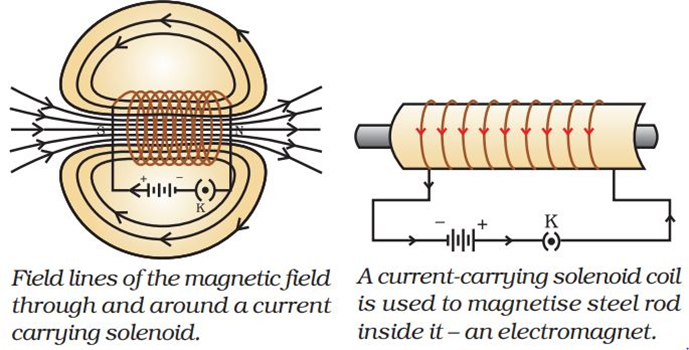
The field lines inside the solenoid are in the form of parallel straight lines. This indicates that the field is uniform inside the solenoid.
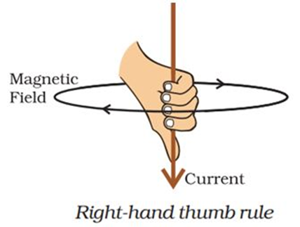
Right-Hand Thumb Rule:
If a straight conductor is held in the right hand in such a way that the thumb points along the direction of the current then the fingers curl in the direction of magnetic field around it.
2. Resistance of a System of Resistors
- Books Name
- SonikaAnandAcademy Science Book
- Publication
- SonikaAnandAcademy
- Course
- CBSE Class 10
- Subject
- Science
2. Resistance of a System of Resistors
- Books Name
- Iti Shree Science Book
- Publication
- Vaishnav Publication
- Course
- CBSE Class 10
- Subject
- Science
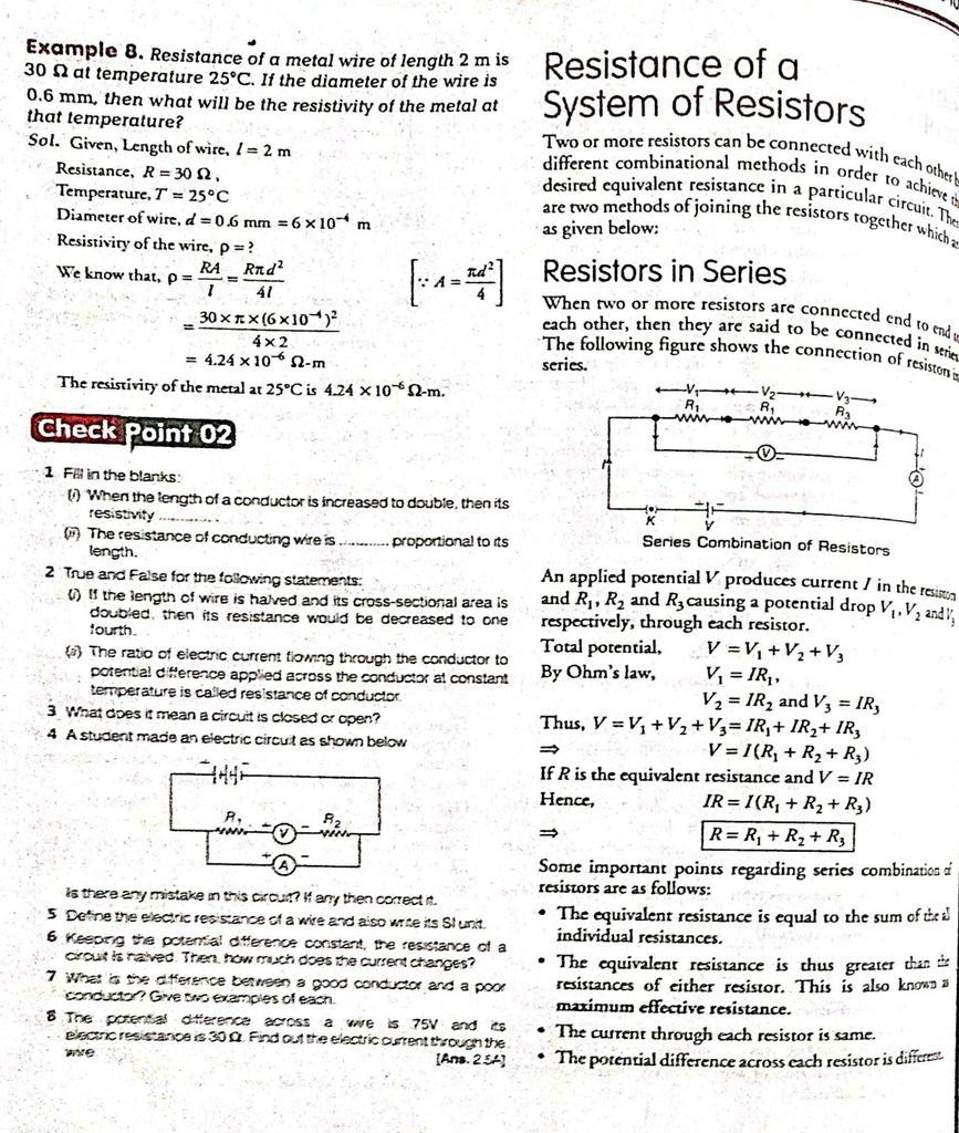
Resistors in series
When two or more resistors are joined in series, then their total resistance is given by the formula-
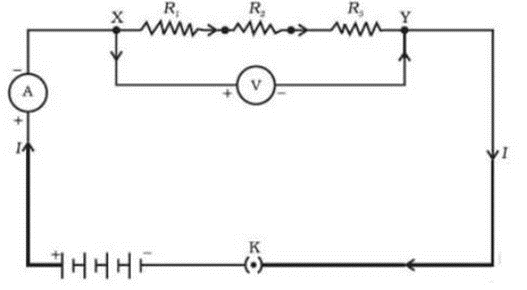
RS = R1 + R2 + R3
The current will remain the same through all resistors. Total voltage is given by-
V = V1 + V2 + V3
Voltage across each resistor is given as –
V1 = lR1
V2 = lR2 [V1 + V2 + V3 = V]
V3 = lR3V = lR
⇒ V = lR1 + lR2 + lR3
lR = l(R1+ R2 + R3)
R = R1 + R2 + R3
Resistors in parallel
In this case, voltage is the same across each resistor and is equal to the applied voltage. The total current is given as-
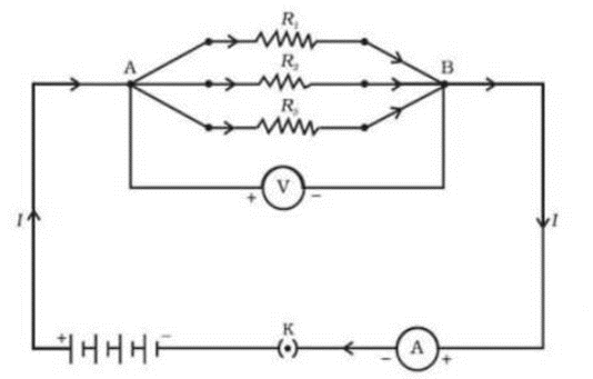
V/R = V/R1 + V/R2 + V/R3
1/Rp = 1/R1 + 1/R2 + 1/R3
Advantages of Parallel Combination over Series Combination
If one component fails in a series combination, then the complete circuit is broken and no component can work properly. Different appliances need different currents.
3. Heating Effects of Electric Current and Electric Power
- Books Name
- SonikaAnandAcademy Science Book
- Publication
- SonikaAnandAcademy
- Course
- CBSE Class 10
- Subject
- Science
3. Heating Effects of Electric Current and Electric Power
- Books Name
- Iti Shree Science Book
- Publication
- Vaishnav Publication
- Course
- CBSE Class 10
- Subject
- Science
Heating effects of Electric Current
When charge Q moves against the potential difference V in time t, the amount of work is given by-
Joules Law of Heating
- The heat produced in a resistor is directly proportional to the square root of the current.
- It is also directly proportional to resistance for a given current.
- Also, directly proportional to the time
H = l2 Rt
Heating Effects of electric current
- The electric laundry iron, electric toaster, electric oven, electric kettle and electric heater are some of the familiar devices based on Joule’s heating.
- Electric heating is also used to produce light in a bulb. The filament of an electric bulb is made up of tungsten because it has a very high melting point and also does not oxidise readily at a high temperature.
- An electric fuse is a safety device to protect the electrical appliance from a short circuit. The fuse is placed in series with the device. It consists of a piece of wire made of a metal or an alloy of appropriate melting point, for example, aluminum, copper, iron, lead etc. If a current larger than the specified value flows through the circuit, the temperature of the fuse wire increases. This melts the fuse wire and breaks the circuit.
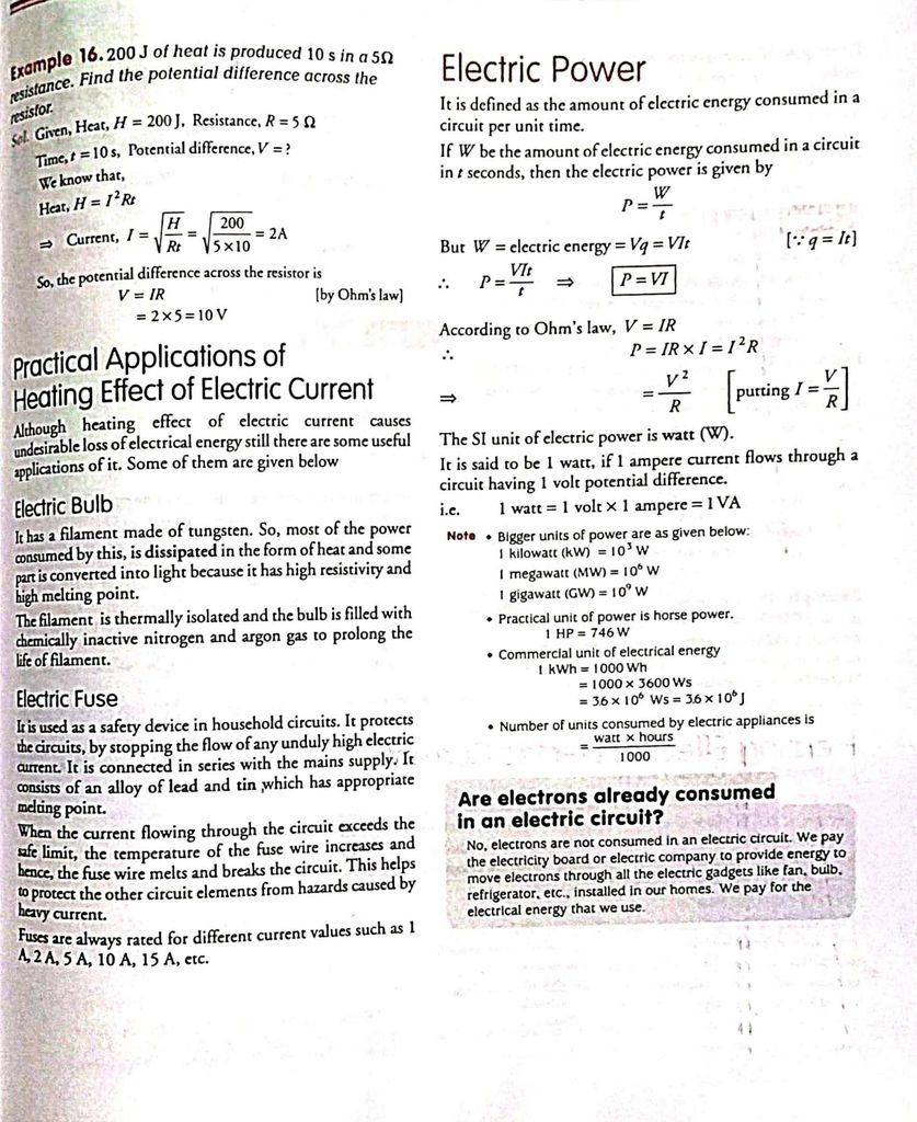
Electric Power
The rate at which electric energy is dissipated or consumed in an electric current. The SI unit of power is Watt.
P = Vl
⇒ P = l2 R = V2/R
The commercial unit of electric energy is a kilowatt-hour (KWh).
Ohm's Law
- Books Name
- SonikaAnandAcademy Science Book
- Publication
- SonikaAnandAcademy
- Course
- CBSE Class 10
- Subject
- Science
Factors on which the Resistance of a Conductor Depends
- Books Name
- SonikaAnandAcademy Science Book
- Publication
- SonikaAnandAcademy
- Course
- CBSE Class 10
- Subject
- Science
Resistance of a System of Resistors
- Books Name
- SonikaAnandAcademy Science Book
- Publication
- SonikaAnandAcademy
- Course
- CBSE Class 10
- Subject
- Science
System of Resistors

Heating Effect of Electric Current
- Books Name
- SonikaAnandAcademy Science Book
- Publication
- SonikaAnandAcademy
- Course
- CBSE Class 10
- Subject
- Science
Electric Power
- Books Name
- SonikaAnandAcademy Science Book
- Publication
- SonikaAnandAcademy
- Course
- CBSE Class 10
- Subject
- Science

2. Force on a Current-Carrying Conductor in a Magnetic Field
- Books Name
- Iti Shree Science Book
- Publication
- Vaishnav Publication
- Course
- CBSE Class 10
- Subject
- Science
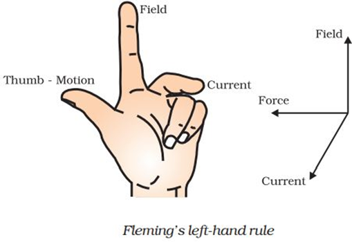
Fleming’s Left Hand Rule
According to this rule, stretch the thumb, forefinger and middle finger of your left hand such that they are mutually perpendicular. If the first finger points in the direction of magnetic field and the second finger in the direction of current, then the thumb will point in the direction of motion or the force acting on the conductor.
Magnetism in Medicine
- Two main organs in the human body where the magnetic field produced is significant, are the heart and the brain.
- The magnetic field inside the body forms the basis of obtaining the images of different body parts through a technique called Magnetic Resonance Imaging (MRI).
- Analysis of these images helps in medical diagnosis.
Electric Motor: An electric motor is a rotating device that converts electrical energy to mechanical energy.
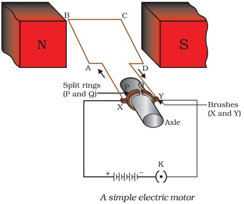
Principle of electric motor: An electric motor works on the principle that when a current carrying rectangular coil is placed perpendicular to the magnetic field it experiences a force which rotates it continuously.
Construction of electric motor:
→ It consists of a rectangular coil ABCD of insulated copper wire.
→ The coil is placed perpendicularly between the two poles of a magnetic field.
→ The ends of the coil are connected to the two halves P and Q of a split ring. Split rings act as a commutator which reverses the flow of current in the circuit.
→ The inner sides of split ring are attached to an axle which is free to rotate.
→ The external edges of the split ring touch two conducting stationary brushes X and Y.
→ These brushes are attached to the battery to complete the circuit.
Working of electric motor:
→ Current in the coil ABCD enters from the source battery through conducting brush X and flows back to the battery through brush Y.
→ Current flows through coil from A to B and then from C to D. The direction of magnetic field is from North to South.
→ By Fleming's left hand rule, the force acting on arm AB pushes it downwards while the force acting on arm CD pushes it upwards.
→ Thus the coil and the axle O rotate anti-clockwise.
→ After half rotation, Q touches brush X and P touches brush Y. Therefore the current in the coil gets reversed along the path DCBA.
→ Now, the current in CD flows from D to C and in AB from B to A.
→ So, CD moves downwards and AB moves upwards.
→ Thus, the coil and the axle keep rotating until the battery is switched off.
Commutator: A device that reverses the direction of flow of current through a circuit is called a commutator.
Significance of commutator: In electric motors, the split ring acts as a commutator. The split ring is used to reverse flow of current to make coil rotate in a single direction. Otherwise, in absence of split the coil would have rotated half in clockwise direction and half in anticlockwise direction.
The commercial motors use
(i) An electromagnet in place of permanent magnet
(ii) Large number of turns of the conducting wire in the current carrying coil and
(iii) A soft iron core on which the coil is wound.
The soft iron core, on which the coil is wound, is called an armature. This enhances the power of the motor.
3.Electromagnetic Induction and Domestic Electric Circuits
- Books Name
- Iti Shree Science Book
- Publication
- Vaishnav Publication
- Course
- CBSE Class 10
- Subject
- Science
What is Galvanometer?
- A galvanometer is a device (instrument) used in a circuit to detect weak electrical voltages and currents.
- It has a coil of a solid laminated horse shoe magnet pivoted (or suspended) between concave pole faces.
- It deflects as an electrical current travels through the coil.
Faraday’s Experiment
In First experiment,
- Faraday connected a coil to a galvanometer.
- A bar magnet was pushed towards the coil, such that the North Pole is pointing towards the coil.
- As the bar magnet is shifted, the pointer in the galvanometer gets deflected, thus indicating the presence of current in the coil under consideration.
Observation:
- When the bar magnet is stationary, the pointer shows no deflection and the motion lasts only till the magnet is in motion.
- Here, the direction of the deflection of the pointer depends upon the direction of motion of the bar magnet.
- Also, when the south pole of the bar magnet is moved towards or away from the coil, the deflections in the galvanometer are opposite to that observed with the north-pole for similar movements.
- Apart from this, the deflection of the pointer is larger or smaller depending upon the speed with which it is pulled towards or away from the coil.
- The same effect is observed when instead of the bar magnet, the coil is moved and the magnet is held stationary.
Observation:
- As we move the second coil towards the primary coil, the pointer in the galvanometer undergoes deflection, which indicates the presence of the electric current in the first coil.
Conclusion:
- The direction of the deflection of the pointer depends upon the direction of motion of the secondary coil towards or away from the primary coil.
- Also, the magnitude of deflection depends upon the speed with which the coil is moved.
- All these results show that the system in the second case is analogous to the system in the first experiment.
In Third experiment,
- From the above two experiments, it was concluded by Faraday that the relative motion between the magnet and the coil resulted in the generation of current in the primary coil.
- But another experiment conducted by Faraday proved that the relative motion between the coils was not really necessary for the current in the primary to be generated.
- In third experiment, he placed two stationary coils and connected one of them to the galvanometer and the other to a battery, through a push-button.
Observation:
As the button was pressed, the galvanometer in the other coil showed a deflection, indicating the presence of current in that coil.
Conclusion:
The deflection in the pointer was temporary and if pressed continuously, the pointer showed no deflection and when the key was released, the deflection occurred in the opposite direction.
Flemming Right Hand Rule
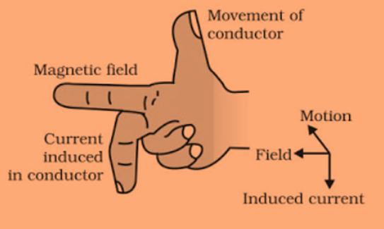
Fleming right hand rule
Hold the forefinger, middle finger and thumb of right hand at right angles to each other. Forefinger points towards the direction of magnetic field, thumb points in the direction of motion of conductor and middle finger shows direction of induced current.
Electric Generator
Electric Energy is a device used to convert mechanical energy into alternating form of electrical energy. It consists of insulated copper wire, magnetic poles, split rings, axle, brushes and galvanometer.
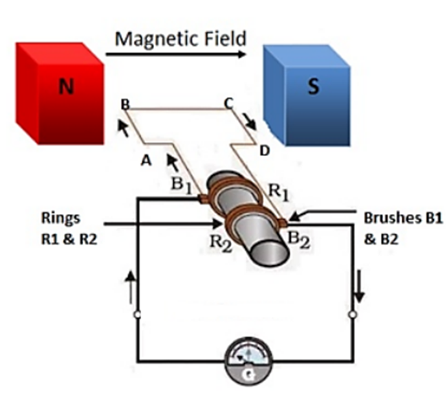
Electric generator
The axle is rotated so that it moves clockwise direction that is AB moves up and CD moves down. After half rotation, CD starts to move up and AB moves down. After every half rotation current changes its direction, this is called AC current.
Domestic Electric Circuits
Three kinds of wires are used in domestic electric circuits.
- Live wire red in colour.
- Neutral wire with black insulation cover
- Earth wire with green insulation cover.
The potential difference between live and neutral wire in India is 220V.
Electric Fuse
- It is a safety device to limit the current in an electric circuit.
- It prevents the electric appliances from damage.
- It is made up of material which has high resistivity and low melting point.